- Joined
- Mar 7, 2007
- Messages
- 648
- Reaction score
- 2,003
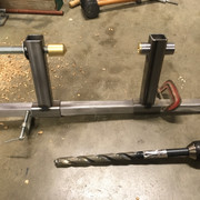
A while back (October of last year) I posted my adventures in making up a 2.75" reamer to correct a flaw in the bore of my lite six pounder full size cannon. If you missed the thread, here is a link Reamer Made to Correct a Cannon Bore
I noted the following in the preamble to that thread......
"I really need another project like I need another root canal......nonetheless, I have begun a refurbishment of the full size cannon I built 50 years ago when I was a junior in high school. Don't ask me why after 50 years I have to do this now, but there are some issues with the gun that have bothered me for 50 years and if I don't get to correcting them now....well.....I don't need to explain any of that to this crowd."
****************************************************************************************************************************************
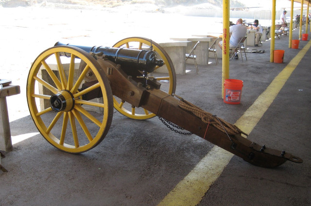
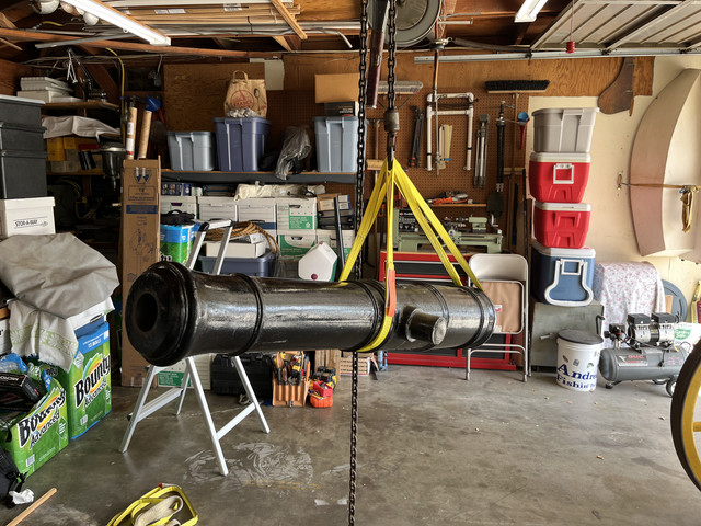
So, many of you have seen these pictures before, but here is the cannon again for those who may not have seen it.......
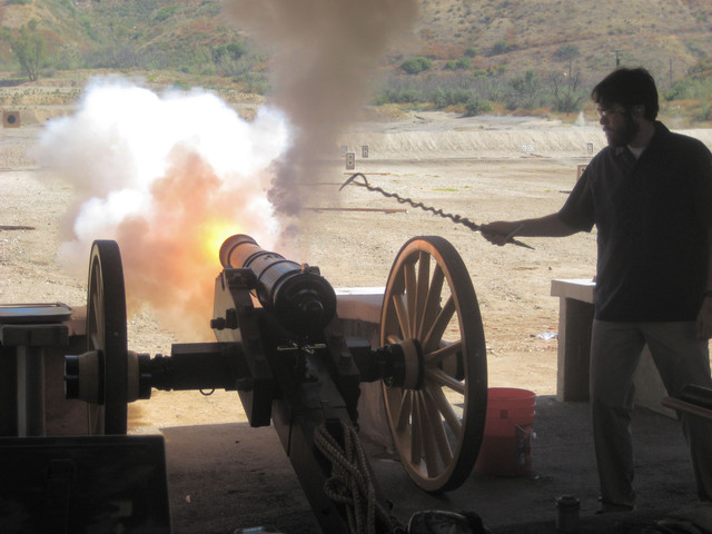
This is the continuation of the story. First of all, at the end of the cannon bore reaming thread I had asked others about Teslong bore scopes. Because of the positive feedback I received, I purchased one and used it to do a much more thorough examination of the bore. Although the diameter of the bore had been corrected to a consistent 2.75", I didn't like some of the porosity I was seeing in the wall at various points. I had been shooting the gun for 50 years with heavy and light charges including charges up to 1.25 pounds of powder behind a 2.75 inch zinc ball....fairly stout for a non combat situation. In all of that, I never had reason to doubt the safety of the barrel. But this gun was cast in 1970 and, since then, almost all the barrels I have seen, iron or brass or bronze, have had steel liners with a welded breech installed. Since I was now intending to correct a lot of the cosmetic deficiencies on the cannon carriage, I decided that it would be best to line the barrel as well. So the reaming exercise had been a bit of wasted effort but I had learned a lot in the process.
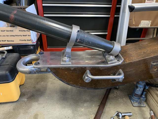
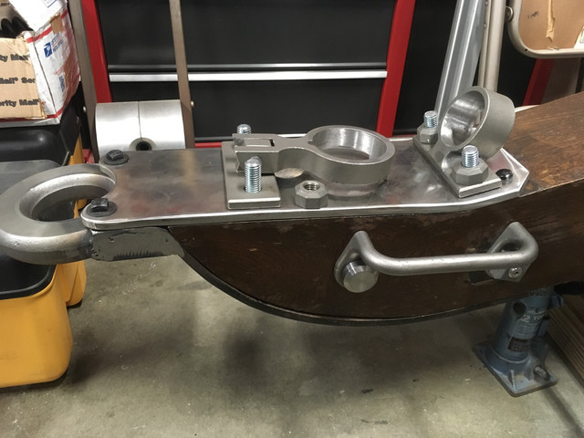
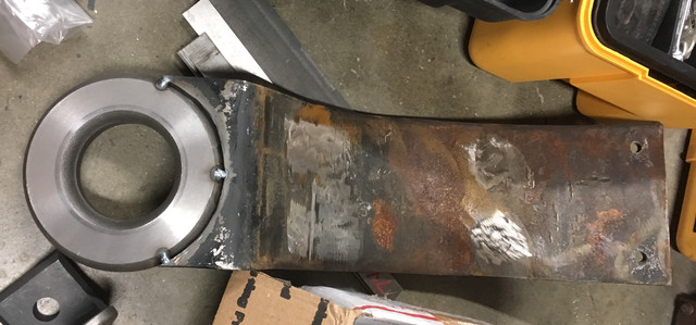
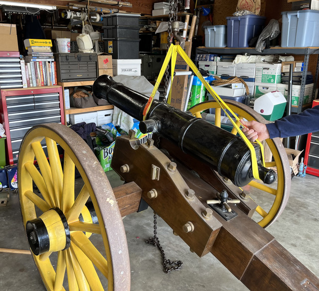
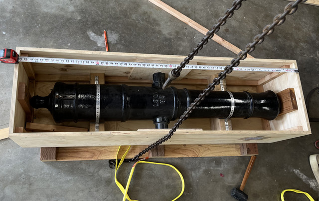
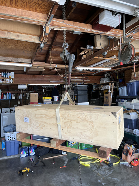
Now re-boring and lining this barrel was far beyond the capability of the machines I own, or have available to me, and demands some specialized skills. So I called Mr. James Olsen at South Bend Replicas (where the barrel was originally cast under the tutelage of Mr. Paul Barnett at what was then "Barney's Cannons"). Jim agreed to rebore the gun to 3.25 inches and install a 1/4" thick DOM steel liner with a welded breech. So last week, I built a substantial crate and managed to wrestle the 600 pounds of barrel off the carriage and into the box. After sealing it up, a friend and I delivered it to a trucking company for shipment back to South Bend.
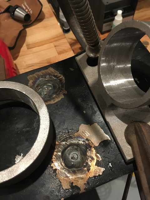
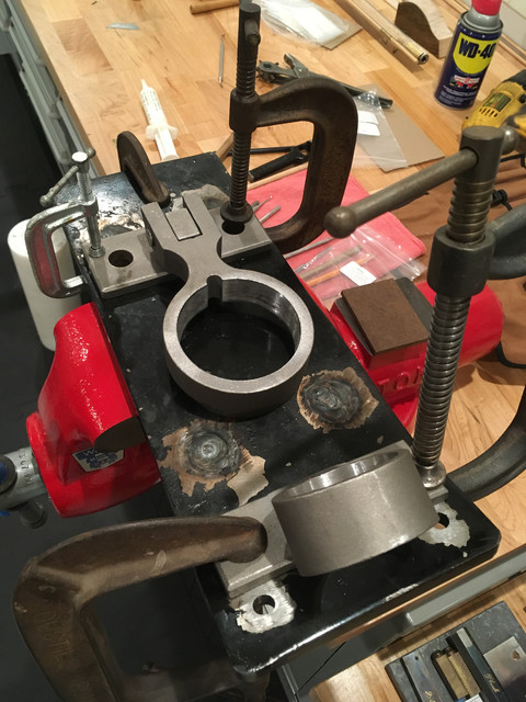
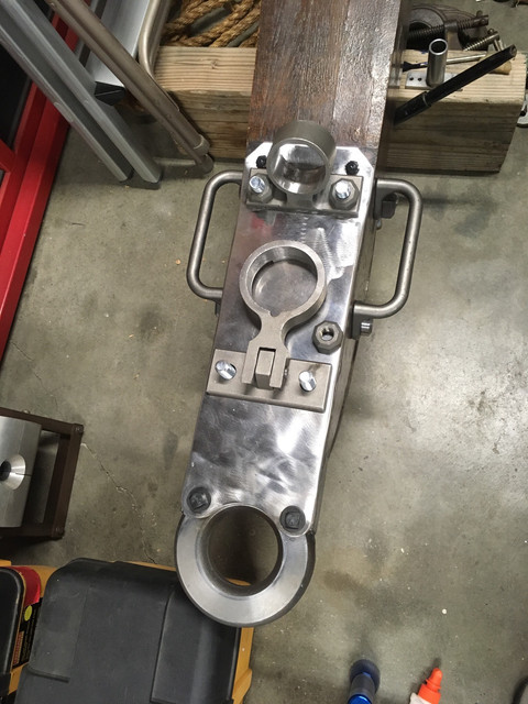
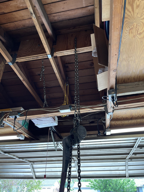
Although that all sounds fairly simple, picking the 600 pound gun barrel up safely off the carriage by myself was not an inconsequential task, so there is some back story..... In 1994, when the Northridge earthquake hit my area, my chimney had broken off at the withers, there was a fair amount of other structural damage inside the house, and the ridge pole in my garage had snapped in two partially collapsing the garage roof. In the process of fixing the garage ridge pole, I had jacked up the broken beam, slipped a second 2 x 12 under it, and then glued and screwed 3/4" plywood stiffeners on both sides of the double beams between the rafters to amalgamate them into a single 3" x 22" ridge beam. With that much beefing up, I figured that ridge pole could take an additional 600 pounds of load.....so I drilled a 2 inch hole through the beam near its top edge and in the center of the garage. With a chain rove through the hole, I hung a ratchet chain hoist on it and used that set up to lift the gun off the carriage.....
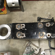
The barrel is now on its way to South Bend. While Jim is doing the lining work, I will continue with the re-build and corrections to the gun carriage itself which will involve a lot of iron and wood work and will keep you posted.
I noted the following in the preamble to that thread......
"I really need another project like I need another root canal......nonetheless, I have begun a refurbishment of the full size cannon I built 50 years ago when I was a junior in high school. Don't ask me why after 50 years I have to do this now, but there are some issues with the gun that have bothered me for 50 years and if I don't get to correcting them now....well.....I don't need to explain any of that to this crowd."
****************************************************************************************************************************************
So, many of you have seen these pictures before, but here is the cannon again for those who may not have seen it.......
This is the continuation of the story. First of all, at the end of the cannon bore reaming thread I had asked others about Teslong bore scopes. Because of the positive feedback I received, I purchased one and used it to do a much more thorough examination of the bore. Although the diameter of the bore had been corrected to a consistent 2.75", I didn't like some of the porosity I was seeing in the wall at various points. I had been shooting the gun for 50 years with heavy and light charges including charges up to 1.25 pounds of powder behind a 2.75 inch zinc ball....fairly stout for a non combat situation. In all of that, I never had reason to doubt the safety of the barrel. But this gun was cast in 1970 and, since then, almost all the barrels I have seen, iron or brass or bronze, have had steel liners with a welded breech installed. Since I was now intending to correct a lot of the cosmetic deficiencies on the cannon carriage, I decided that it would be best to line the barrel as well. So the reaming exercise had been a bit of wasted effort but I had learned a lot in the process.
Now re-boring and lining this barrel was far beyond the capability of the machines I own, or have available to me, and demands some specialized skills. So I called Mr. James Olsen at South Bend Replicas (where the barrel was originally cast under the tutelage of Mr. Paul Barnett at what was then "Barney's Cannons"). Jim agreed to rebore the gun to 3.25 inches and install a 1/4" thick DOM steel liner with a welded breech. So last week, I built a substantial crate and managed to wrestle the 600 pounds of barrel off the carriage and into the box. After sealing it up, a friend and I delivered it to a trucking company for shipment back to South Bend.
Although that all sounds fairly simple, picking the 600 pound gun barrel up safely off the carriage by myself was not an inconsequential task, so there is some back story..... In 1994, when the Northridge earthquake hit my area, my chimney had broken off at the withers, there was a fair amount of other structural damage inside the house, and the ridge pole in my garage had snapped in two partially collapsing the garage roof. In the process of fixing the garage ridge pole, I had jacked up the broken beam, slipped a second 2 x 12 under it, and then glued and screwed 3/4" plywood stiffeners on both sides of the double beams between the rafters to amalgamate them into a single 3" x 22" ridge beam. With that much beefing up, I figured that ridge pole could take an additional 600 pounds of load.....so I drilled a 2 inch hole through the beam near its top edge and in the center of the garage. With a chain rove through the hole, I hung a ratchet chain hoist on it and used that set up to lift the gun off the carriage.....
The barrel is now on its way to South Bend. While Jim is doing the lining work, I will continue with the re-build and corrections to the gun carriage itself which will involve a lot of iron and wood work and will keep you posted.


")