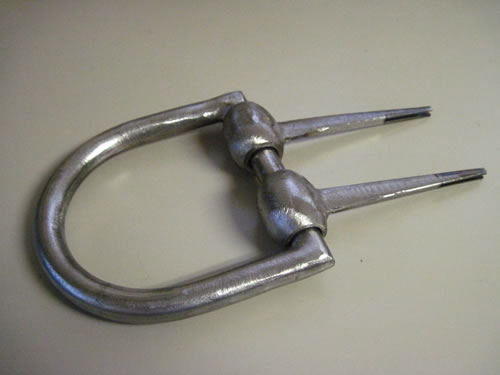
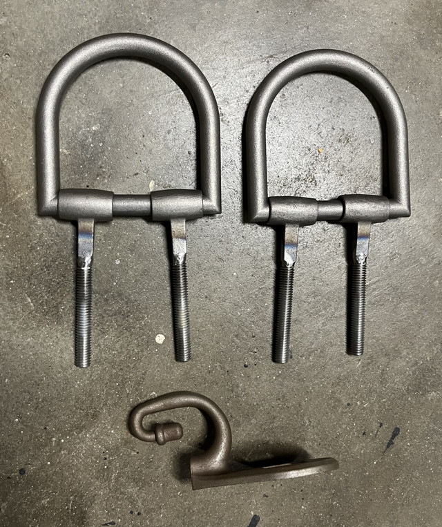
It has been a year since I had any time to work on finishing the re-build of this cannon and two years since I started the project. I am determined to have the gun back together and operational by the 4th of July this year. When I had to stop work last year I was in the midst of upgrading all of the "irons" on the carriage. I had completed rebuilding or replacing several items but had stopped short of a few that remained. Some of the items that needed to be replaced were the axel strap and the the two under straps that hold the instrument hooks. The axel strap runs along the underside of the trail and surrounds the axel where the trail rests on it. On a real 12 pound Napoleon, it was made out of half inch thick iron about 3 inches wide. The two under straps, also made of half inch thick iron, attach to the underside of each cheek and surround the axel as well. The forward end of the under straps was forged into a tube that supported the instrument hooks that held rammers and a worm.
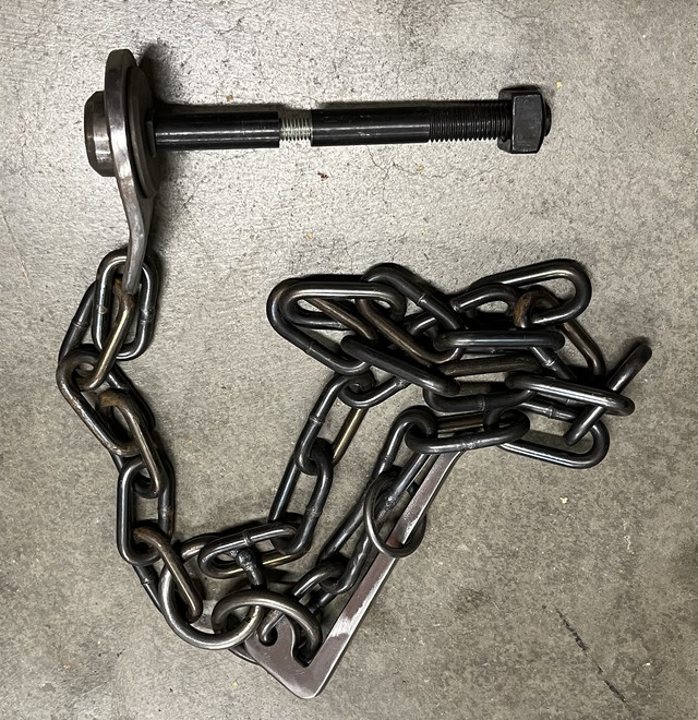
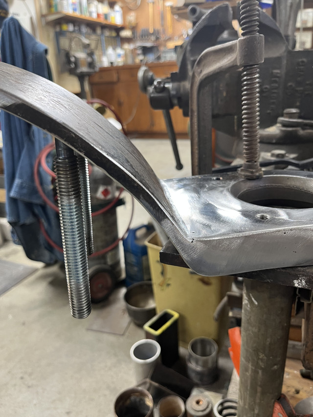
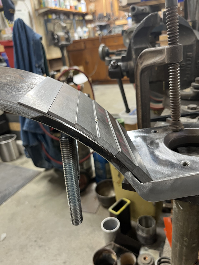
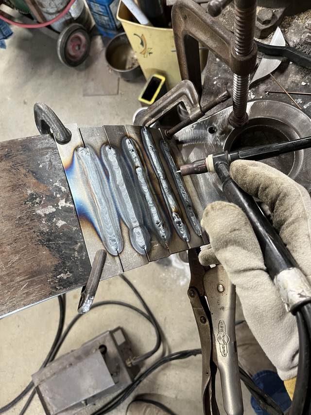
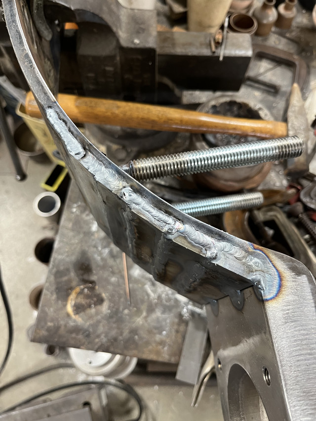
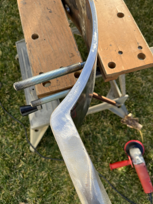
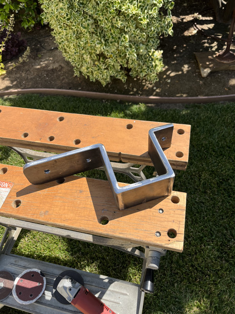
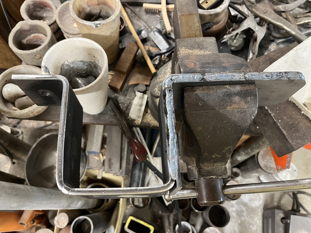
When I built the gun in 1970, I could heat and bend quarter inch thick iron straps to form these parts. But with my "wheel barrel full of burning charcoal" forge, and using the man hole cover in the street as an anvil, I couldn't quite make the parts out of 1/2" steel and bend them to fit properly all by me "onesies"....so I made them 1/4" thick and they have always looked a little on the "whimpy" side. So I thought about just remaking them out of the correct thickness material and replacing the original ones entirely. However, in keeping with my desire to keep as much of the original pieces as possible, I decided just to double them up. Using the original 1/4" thick straps, I have started cutting additional pieces of 1/4" material and welding them to the original straps now resulting in the appropriate 1/2" thickness. Here is a picture of one of the under straps in the vise on my weld table with part of it doubled up. I am welding all along the seam on the edges so once the welds are all ground smooth, the part will look like it was made of 1/2" material all along. Basically, it is the same method I used to build up the lunette I showed earlier in this thread.....
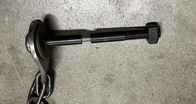
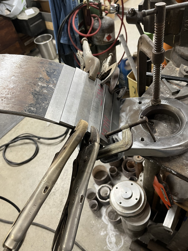
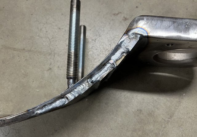
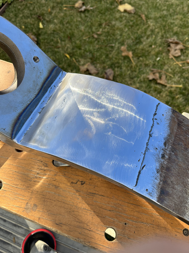
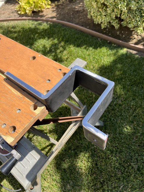
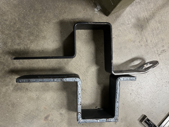
The next photo shows the right under strap (with all the edge welding completed but not yet ground smooth) and the original axel strap in the unmodified 1/4" thick condition.
I will get the welding done on the rest of this and then the grinding in the next few days. Once this is done, the next step is to start in on the wood work and refinishing of the trail and cheeks.