Will do. Thanks
-
This community needs YOUR help today. We rely 100% on Supporting Memberships to fund our efforts. With the ever increasing fees of everything, we need help. We need more Supporting Members, today. Please invest back into this community. I will ship a few decals too in addition to all the account perks you get.

Sign up here: https://www.muzzleloadingforum.com/account/upgrades -
Friends, our 2nd Amendment rights are always under attack and the NRA has been a constant for decades in helping fight that fight.
We have partnered with the NRA to offer you a discount on membership and Muzzleloading Forum gets a small percentage too of each membership, so you are supporting both the NRA and us.
Use this link to sign up please; https://membership.nra.org/recruiters/join/XR045103
You are using an out of date browser. It may not display this or other websites correctly.
You should upgrade or use an alternative browser.
You should upgrade or use an alternative browser.
Building the King's Muskets and a Bit More
- Thread starter dave_person
- Start date


Help Support Muzzleloading Forum:
This site may earn a commission from merchant affiliate
links, including eBay, Amazon, and others.
thank you sir: most excellent as always  i love mrs. bess
i love mrs. bessSooty Scot
40 Cal
- Joined
- May 2, 2022
- Messages
- 220
- Reaction score
- 164
Not at all. Your posts are all great educational pieces. Thank you.Hi Folks,
Today Maria and I will start our thread on building copies of the British "King's Pattern" (Brown Bess) musket and making them as historically accurate as our circumstances permit. I hope you will find this thread entertaining and useful. I apologize up front for the amount of text and some of you may think me pretentious posting this thread but so be it. I believe in education and think this forum is an ideal venue for disseminating information that I know some will value. I gave a seminar at the Kempton's Gunmakers Fair about the Brown Bess and this thread is a follow up to that talk.
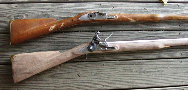
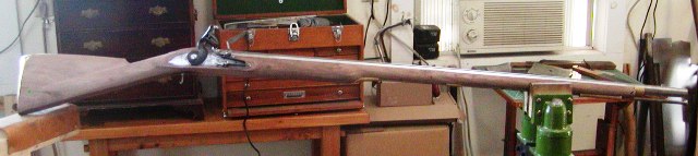
Maria and I are making 2 short land and a long land British musket, as well as an Elliot light dragoon carbine. We will focus first on the 2 short land muskets. Here is an example:
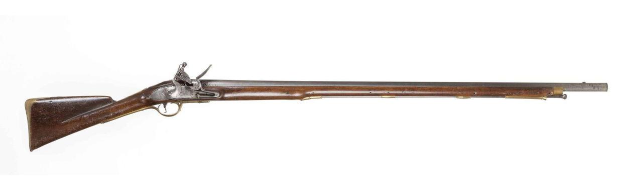
It is a pattern 1769 short land musket probably issued during the time of our Revolutionary War. These muskets have shorter 42" barrels differentiating them from the long land muskets with 46" barrels. They and their later variants were the primary British muskets during the latter period of the war (late 1777 - 1783). Early in the war, older pattern long land muskets predominated but not exclusively. I describe the muskets as long or short land and by dated patterns. Let me spend a little time explaining those details. The "land" designation differentiated the guns from those designed and issued for "sea" service. The patterns refer to research by DeWitt Bailey who created a viable taxonomy for British muskets based dated warrants specifying guns as patterns. Previously, collectors and historians focused on "models" of the muskets, something never adopted by British Ordnance. It was simply a convenience for collectors and it glossed over many details. George Moller complicated things by referring to different types within models adding further confusion and adding nothing to the discussion. Bailey cleared it all up by linking dated British government warrant specifications to the various muskets, revealing the different patterns associated with specific dates. Moreover, the British never referred to the musket by models or types. It was always the old King's pattern and the new King's pattern. Here is a sample of the patterns that were used in North America during the 18th century up to and during the Rev War.
Pattern 1730 Long Land First Official King's Musket

Most were upgraded with a newer lock with pan bridle, stronger trigger guard, and often a brass nose band when issued for service in America.
Pattern 1742 Long Land, the workhorse during the French & Indian War
All the lock moldings were gone, the gun simplified but made more massive. Many were converted to steel rammers and fitted with brass nose bands.
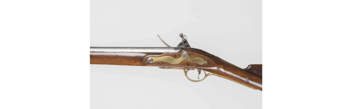
Pattern 1756 Long Land Musket, last of the long lands.
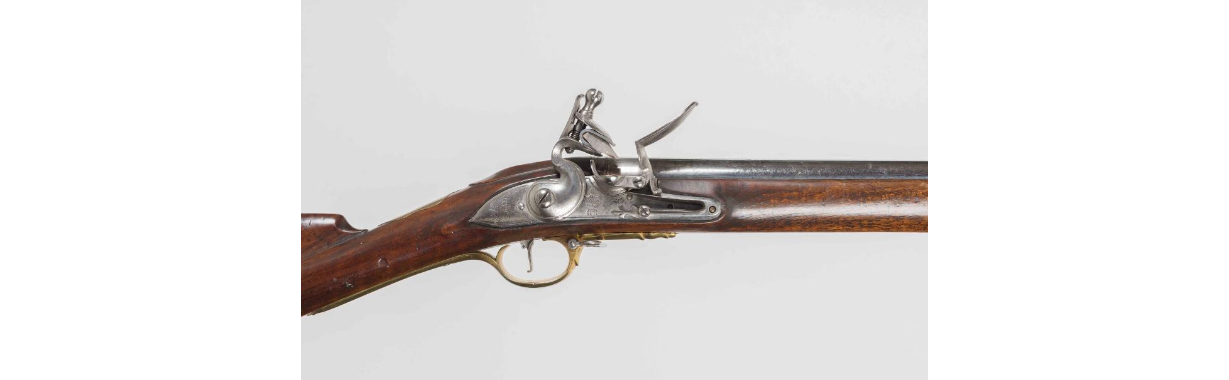
New lock with straighter lock plate, designed for steel rammer, long trumpet front ramrod pipe, cast brass nose cap. These muskets were not issued to troops in America during the F&I war. They were the primary muskets issued to British troops during the first 3 years of the Revolution.
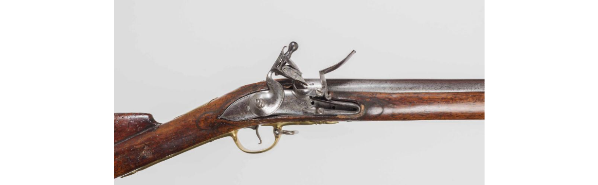
Pattern 1769 Short Land Musket.
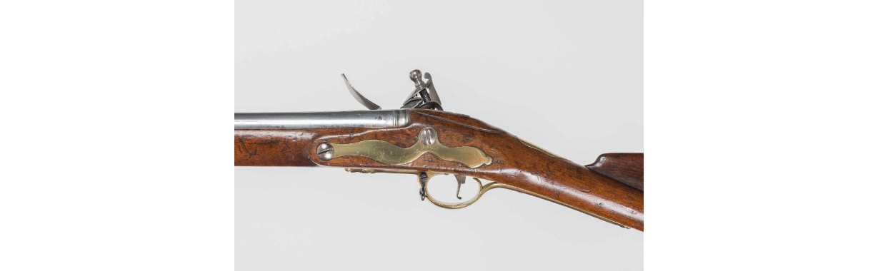
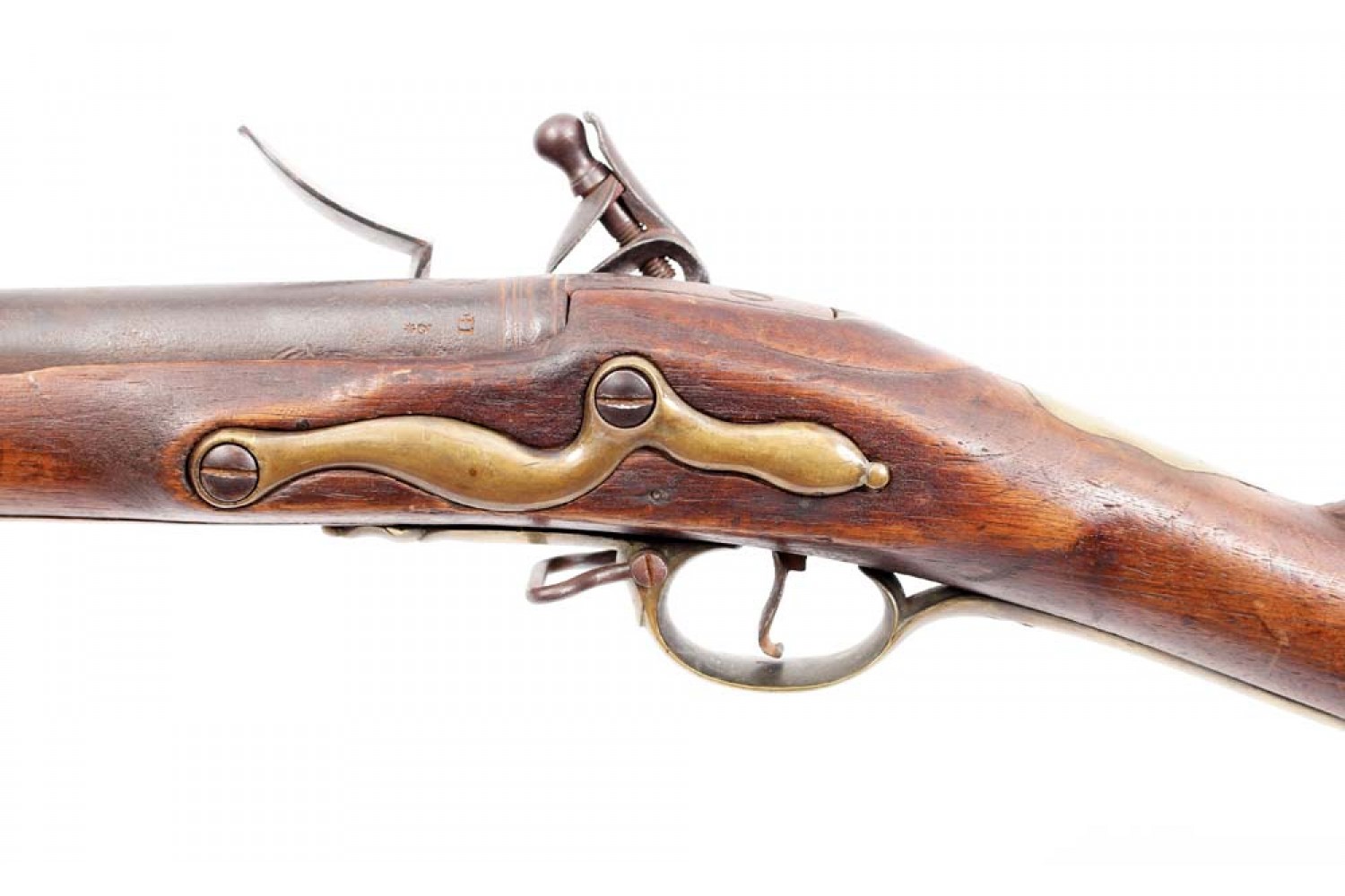
Same lock as pattern 1756, shorter 42" barrel, simplified buttplate, and flat side plate. The first of these muskets arrived in America with troops supported by the Irish establishment. Hence, they were marked "Dublin Castle" . By the 1776 New York campaign, many "Tower" marked short lands made their way to America. After about 1777, an updated variant of the pattern 1769 began to show up with British troops. This was the pattern 1777.
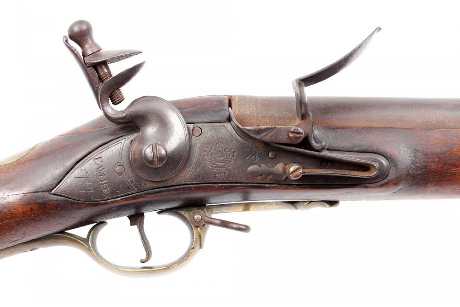
It had a new simplified lock showing 2 screws behind the flint cock because it used a short sear spring, the finial on the feather spring was simplified, and so was the flintcock. The top jaw screw was given a hole for a tightening bar. Additionally, the mouth of the second ramrod pipe was flared allowing easier entry of the ramrod.
There are other variants, but these are the major ones aasociated with American history.
dave
- Joined
- Nov 1, 2018
- Messages
- 3,224
- Reaction score
- 2,285
Hi Folks,
Today Maria and I will start our thread on building copies of the British "King's Pattern" (Brown Bess) musket and making them as historically accurate as our circumstances permit. I hope you will find this thread entertaining and useful. I apologize up front for the amount of text and some of you may think me pretentious posting this thread but so be it. I believe in education and think this forum is an ideal venue for disseminating information that I know some will value. I gave a seminar at the Kempton's Gunmakers Fair about the Brown Bess and this thread is a follow up to that talk.
Maria and I are making 2 short land and a long land British musket, as well as an Elliot light dragoon carbine. We will focus first on the 2 short land muskets. Here is an example:
It is a pattern 1769 short land musket probably issued during the time of our Revolutionary War. These muskets have shorter 42" barrels differentiating them from the long land muskets with 46" barrels. They and their later variants were the primary British muskets during the latter period of the war (late 1777 - 1783). Early in the war, older pattern long land muskets predominated but not exclusively. I describe the muskets as long or short land and by dated patterns. Let me spend a little time explaining those details. The "land" designation differentiated the guns from those designed and issued for "sea" service. The patterns refer to research by DeWitt Bailey who created a viable taxonomy for British muskets based dated warrants specifying guns as patterns. Previously, collectors and historians focused on "models" of the muskets, something never adopted by British Ordnance. It was simply a convenience for collectors and it glossed over many details. George Moller complicated things by referring to different types within models adding further confusion and adding nothing to the discussion. Bailey cleared it all up by linking dated British government warrant specifications to the various muskets, revealing the different patterns associated with specific dates. Moreover, the British never referred to the musket by models or types. It was always the old King's pattern and the new King's pattern. Here is a sample of the patterns that were used in North America during the 18th century up to and during the Rev War.
Pattern 1730 Long Land First Official King's Musket
Most were upgraded with a newer lock with pan bridle, stronger trigger guard, and often a brass nose band when issued for service in America.
Pattern 1742 Long Land, the workhorse during the French & Indian War
All the lock moldings were gone, the gun simplified but made more massive. Many were converted to steel rammers and fitted with brass nose bands.
Pattern 1756 Long Land Musket, last of the long lands.
New lock with straighter lock plate, designed for steel rammer, long trumpet front ramrod pipe, cast brass nose cap. These muskets were not issued to troops in America during the F&I war. They were the primary muskets issued to British troops during the first 3 years of the Revolution.
Pattern 1769 Short Land Musket.
Same lock as pattern 1756, shorter 42" barrel, simplified buttplate, and flat side plate. The first of these muskets arrived in America with troops supported by the Irish establishment. Hence, they were marked "Dublin Castle" . By the 1776 New York campaign, many "Tower" marked short lands made their way to America. After about 1777, an updated variant of the pattern 1769 began to show up with British troops. This was the pattern 1777.
It had a new simplified lock showing 2 screws behind the flint cock because it used a short sear spring, the finial on the feather spring was simplified, and so was the flintcock. The top jaw screw was given a hole for a tightening bar. Additionally, the mouth of the second ramrod pipe was flared allowing easier entry of the ramrod.
There are other variants, but these are the major ones aasociated with American history.
dave
Interesting on the 1756 long land Dave.
It appears like the second rammer pipe is flared, maybe it’s a Pratts improvement.
I know they made these long lands up until 1790, not sure how significant later productions were though.
- Joined
- Nov 26, 2005
- Messages
- 5,019
- Reaction score
- 9,973
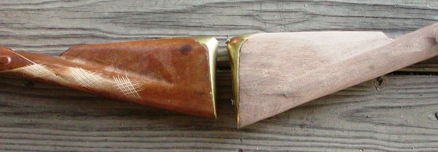
Hi Nick,
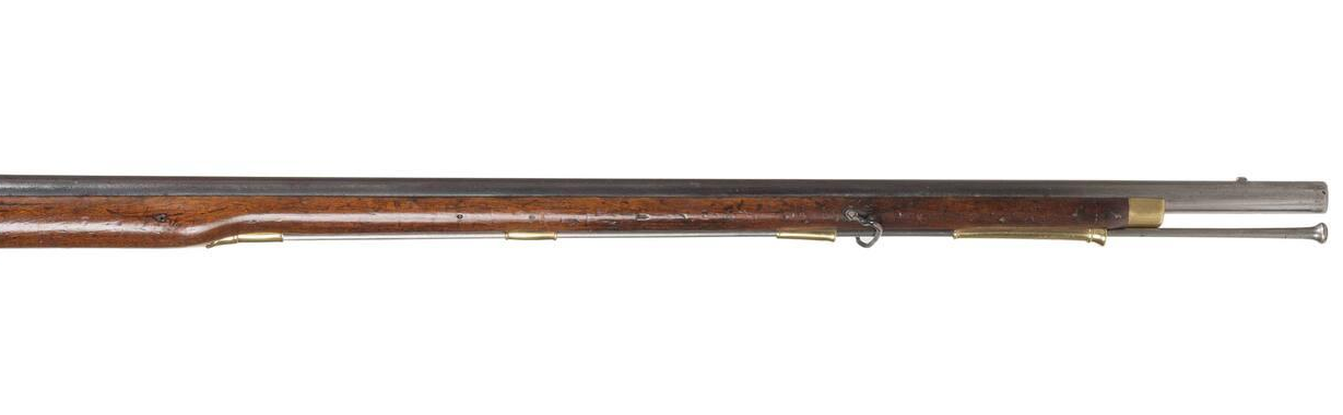
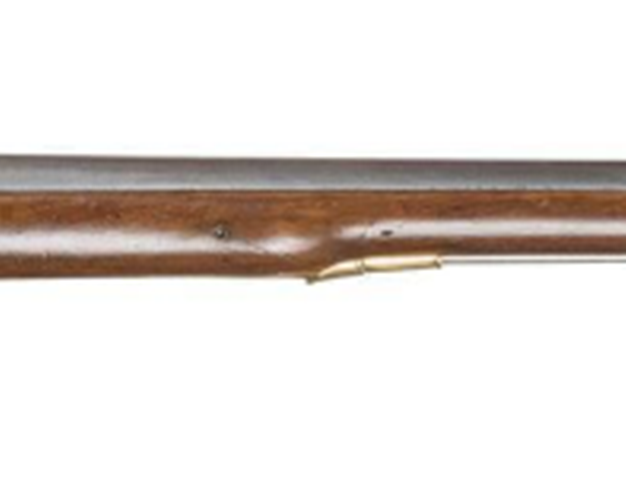
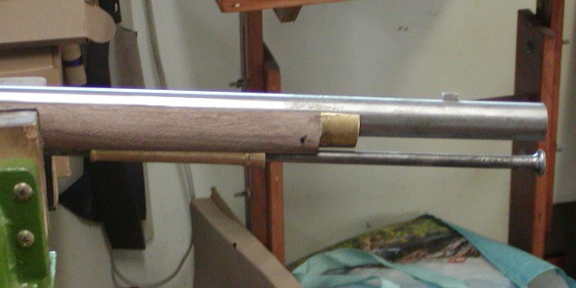
I am afraid I used the wrong photo. The forend photo is of a pattern 1777 identical to the one below it. Nevertheless, it shows the key new features of the 1756, the cast nose cap, steel rammer, long trumpet first pipe. The Pratt pipe is of course later.
dave
I am afraid I used the wrong photo. The forend photo is of a pattern 1777 identical to the one below it. Nevertheless, it shows the key new features of the 1756, the cast nose cap, steel rammer, long trumpet first pipe. The Pratt pipe is of course later.
dave
- Joined
- Nov 26, 2005
- Messages
- 5,019
- Reaction score
- 9,973
Hi,
The barrel of the King's musket is attached to the stock using the tang bolt, 3 barrel pins, and the forward sling swivel screw. This is another case where the Italian and Japanese repros get it wrong. Neither has a lug on the barrel for the sling swivel, rather they just have a incorrectly positioned 4th barrel pin. The swivel is completely supported by the stock. The barrel pins should be located 10 1/8", 18 3/8", and 36 1/4" from the breech. The stock ends 4 1/2" from the muzzle. The forward sling swivel screw is 28 7/8" from the breech and is positioned so the swivel will come to rest on the second ramrod pipe such that the sling will not block the ramrod channel.
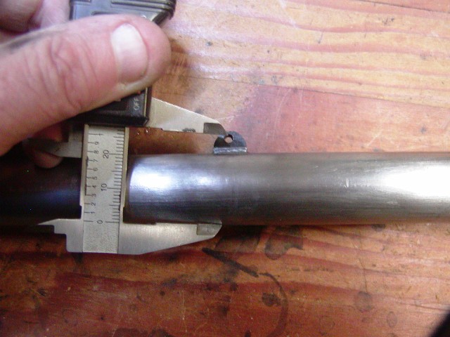
The original barrels were heavier and had thicker walls than the modern repros. The barrel and swivel lugs were actually dovetailed into the barrels and then brazed or soldered. On the repro barrels we are using, we don't dovetail the lugs but simply solder them on. I use either Hi-Force 44 or Stay Bright low temperature silver bearing solder and sweat the solder into the joint by holding the fluxed lug on the barrel with wire, placing solder on the upper edge, and then heating from below to draw the solder toward the heat.
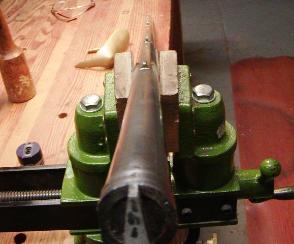
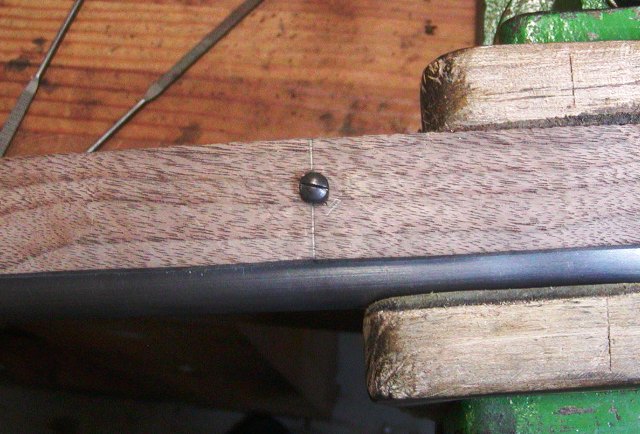
In this project, we are using the old lugs, which are already drilled for pins, which makes it easy to wire them in place for soldering. We made new lugs for the sling swivels. Since the bases of the lugs sit very proud from the barrel, we have to inlet them into the stock.
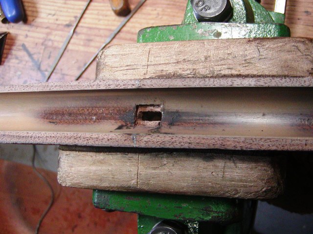
The barrel pin lugs are already drilled so we have to drill the stocks accordingly to hit the holes. Not a problem. Just trim most of the excess stock off the blank, square up the sides and take good measurements to locate the holes on the wood. Lugs on these muskets show on the bottom of the ramrod channel, which makes it really easy to locate the lugs and the hole positions on the stock.
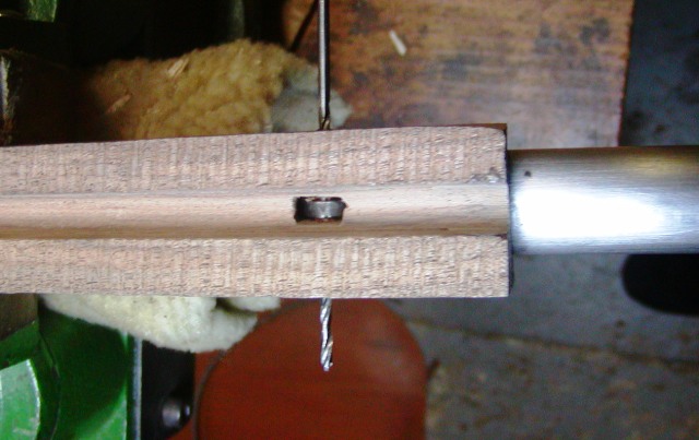
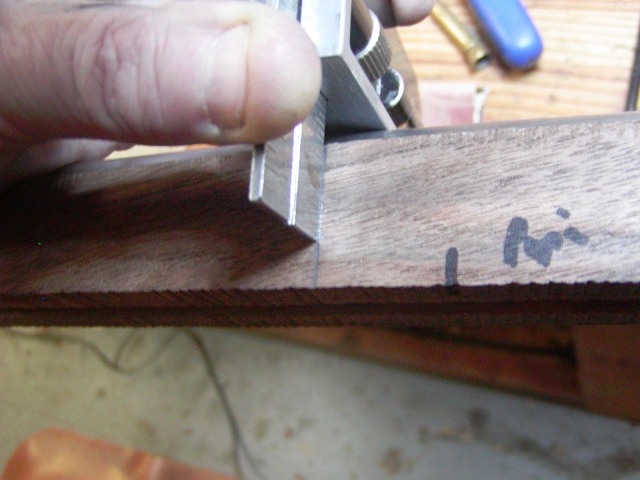

I use 3/32" pins for the barrel pins and then drill a hole for the sling swivel large enough for a 6-32 bolt.
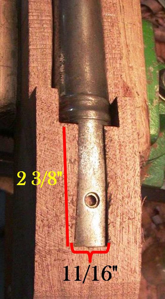
The breech plugs on the Japanese and Italian repros are real pains in the butt. The bolsters are much more tapered and smaller than the originals. We remove the plugs before inletting the barrels. On some of the early Pedersoli Besses, the threads on the plug do not reach the end of the threads in the barrel. They are about 2 threads short, exposing those threads to powder fouling. Since many of these muskets have been used for years without problems, I don't think there is any safety issue but there is a corrosion issue because it is hard to clean fouling out of those exposed threads. On these barrels, we rebreech the plugs so they cover all the threads. This requires filing the back of the barrel and also grinding away the flange on the plug that caps the end of the threads. That flange prevents the plug from seating deeper in the threads. Rebreeching will move the plug in about 1/16"-3/32". The vent hole will be closer to the face of the plug but that is not a problem and the pans on the locks still line up nicely with the ends of the breeches. Also grind away any radius where the bolster meets the tang.
Inletting the tang is not hard but first measure it. It should be 2 5/16" - 2 3/8" long, 9/16" wide at the barrel flaring to 11/16" wide at the end. If it is small, beat it.
Shape and file draft on it, install in the barrel and inlet it. The severely tapered bolsters on the repros are a pain to inlet and Pedersoli doesn't even try to fit them precisely in the stocks. We do a proper job of it.
dave
The barrel of the King's musket is attached to the stock using the tang bolt, 3 barrel pins, and the forward sling swivel screw. This is another case where the Italian and Japanese repros get it wrong. Neither has a lug on the barrel for the sling swivel, rather they just have a incorrectly positioned 4th barrel pin. The swivel is completely supported by the stock. The barrel pins should be located 10 1/8", 18 3/8", and 36 1/4" from the breech. The stock ends 4 1/2" from the muzzle. The forward sling swivel screw is 28 7/8" from the breech and is positioned so the swivel will come to rest on the second ramrod pipe such that the sling will not block the ramrod channel.
The original barrels were heavier and had thicker walls than the modern repros. The barrel and swivel lugs were actually dovetailed into the barrels and then brazed or soldered. On the repro barrels we are using, we don't dovetail the lugs but simply solder them on. I use either Hi-Force 44 or Stay Bright low temperature silver bearing solder and sweat the solder into the joint by holding the fluxed lug on the barrel with wire, placing solder on the upper edge, and then heating from below to draw the solder toward the heat.
In this project, we are using the old lugs, which are already drilled for pins, which makes it easy to wire them in place for soldering. We made new lugs for the sling swivels. Since the bases of the lugs sit very proud from the barrel, we have to inlet them into the stock.
The barrel pin lugs are already drilled so we have to drill the stocks accordingly to hit the holes. Not a problem. Just trim most of the excess stock off the blank, square up the sides and take good measurements to locate the holes on the wood. Lugs on these muskets show on the bottom of the ramrod channel, which makes it really easy to locate the lugs and the hole positions on the stock.
I use 3/32" pins for the barrel pins and then drill a hole for the sling swivel large enough for a 6-32 bolt.
The breech plugs on the Japanese and Italian repros are real pains in the butt. The bolsters are much more tapered and smaller than the originals. We remove the plugs before inletting the barrels. On some of the early Pedersoli Besses, the threads on the plug do not reach the end of the threads in the barrel. They are about 2 threads short, exposing those threads to powder fouling. Since many of these muskets have been used for years without problems, I don't think there is any safety issue but there is a corrosion issue because it is hard to clean fouling out of those exposed threads. On these barrels, we rebreech the plugs so they cover all the threads. This requires filing the back of the barrel and also grinding away the flange on the plug that caps the end of the threads. That flange prevents the plug from seating deeper in the threads. Rebreeching will move the plug in about 1/16"-3/32". The vent hole will be closer to the face of the plug but that is not a problem and the pans on the locks still line up nicely with the ends of the breeches. Also grind away any radius where the bolster meets the tang.
Inletting the tang is not hard but first measure it. It should be 2 5/16" - 2 3/8" long, 9/16" wide at the barrel flaring to 11/16" wide at the end. If it is small, beat it.
Shape and file draft on it, install in the barrel and inlet it. The severely tapered bolsters on the repros are a pain to inlet and Pedersoli doesn't even try to fit them precisely in the stocks. We do a proper job of it.
dave
- Joined
- Nov 1, 2018
- Messages
- 3,224
- Reaction score
- 2,285
Hi,
The barrel of the King's musket is attached to the stock using the tang bolt, 3 barrel pins, and the forward sling swivel screw. This is another case where the Italian and Japanese repros get it wrong. Neither has a lug on the barrel for the sling swivel, rather they just have a incorrectly positioned 4th barrel pin. The swivel is completely supported by the stock. The barrel pins should be located 10 1/8", 18 3/8", and 36 1/4" from the breech. The stock ends 4 1/2" from the muzzle. The forward sling swivel screw is 28 7/8" from the breech and is positioned so the swivel will come to rest on the second ramrod pipe such that the sling will not block the ramrod channel.
The original barrels were heavier and had thicker walls than the modern repros. The barrel and swivel lugs were actually dovetailed into the barrels and then brazed or soldered. On the repro barrels we are using, we don't dovetail the lugs but simply solder them on. I use either Hi-Force 44 or Stay Bright low temperature silver bearing solder and sweat the solder into the joint by holding the fluxed lug on the barrel with wire, placing solder on the upper edge, and then heating from below to draw the solder toward the heat.
In this project, we are using the old lugs, which are already drilled for pins, which makes it easy to wire them in place for soldering. We made new lugs for the sling swivels. Since the bases of the lugs sit very proud from the barrel, we have to inlet them into the stock.
The barrel pin lugs are already drilled so we have to drill the stocks accordingly to hit the holes. Not a problem. Just trim most of the excess stock off the blank, square up the sides and take good measurements to locate the holes on the wood. Lugs on these muskets show on the bottom of the ramrod channel, which makes it really easy to locate the lugs and the hole positions on the stock.
I use 3/32" pins for the barrel pins and then drill a hole for the sling swivel large enough for a 6-32 bolt.
The breech plugs on the Japanese and Italian repros are real pains in the butt. The bolsters are much more tapered and smaller than the originals. We remove the plugs before inletting the barrels. On some of the early Pedersoli Besses, the threads on the plug do not reach the end of the threads in the barrel. They are about 2 threads short, exposing those threads to powder fouling. Since many of these muskets have been used for years without problems, I don't think there is any safety issue but there is a corrosion issue because it is hard to clean fouling out of those exposed threads. On these barrels, we rebreech the plugs so they cover all the threads. This requires filing the back of the barrel and also grinding away the flange on the plug that caps the end of the threads. That flange prevents the plug from seating deeper in the threads. Rebreeching will move the plug in about 1/16"-3/32". The vent hole will be closer to the face of the plug but that is not a problem and the pans on the locks still line up nicely with the ends of the breeches. Also grind away any radius where the bolster meets the tang.
Inletting the tang is not hard but first measure it. It should be 2 5/16" - 2 3/8" long, 9/16" wide at the barrel flaring to 11/16" wide at the end. If it is small, beat it.
Shape and file draft on it, install in the barrel and inlet it. The severely tapered bolsters on the repros are a pain to inlet and Pedersoli doesn't even try to fit them precisely in the stocks. We do a proper job of it.
dave
Regarding the extra threads in the breech, i had that issue also recently. I sent the barrel off to Bobby Hoyt, he welded on a shim to the face of the plug and rethreaded it.
I recently found that same issue on a few Indian made muskets, however it was far worse, the threads were about 1/2 too deep. The plug on the Indian musket came out without a fight too, which kind of concerned me, after I inspected I saw that the threads were extremely shallow, and there was no interface between the plug and breech, its just a straight tube.
I’ve had the opportunity recently to also unbreech a few originals, the threads are extremely wide and course, done very well on this charleville barrel.
Attachments


- Joined
- Nov 26, 2005
- Messages
- 5,019
- Reaction score
- 9,973
Hi,
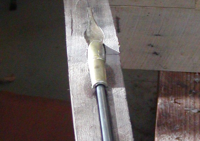
Let's shift to the ramrod pipes. The short land muskets have 4, a long trumpet forward pipe, 2 short middle pipes, and a rear pipe. The long front pipe is 4 1/8" long and the mouth of the pipe is 1 7/8" from the forend of the stock. The front of the second pipe is 3 1/4" from the rear of the front pipe. It is 1 3/8" long and the rear of the pipe is 5 7/8" from the front of the third pipe. The third pipe is identical to the second and its rear is 5 3/4" from the front of the rear pipe. The rear pipe has a barrel 1 5/16" long attached to a tang 3 3/16" long. The rear pipe also has a rod retaining spring attached to the back of the tube. The forward pipes are not hard to inlet but the rear is a challenge. Be aware the tabs can show in the barrel channel so cut slots for them right through. The rear pipe has a tooth on the end of the tang that is supposed to anchor the rear of tang down in the wood. My experience is that the tangs are thick brass and don't need the spur to hold in place. I usually grind them off, which simplifies inletting a lot.
When you inlet the rear pipe, understand that the pipe widens to the rear. Don't try and inlet it so the barrel of the pipe is parallel with the ramrod. It flares toward the rear making it look like the pipe is inlet leaning forward.
The trumpet forward pipe and middle barrel pipes are easy to inlet using a couple of gouges and a stab in chisel.
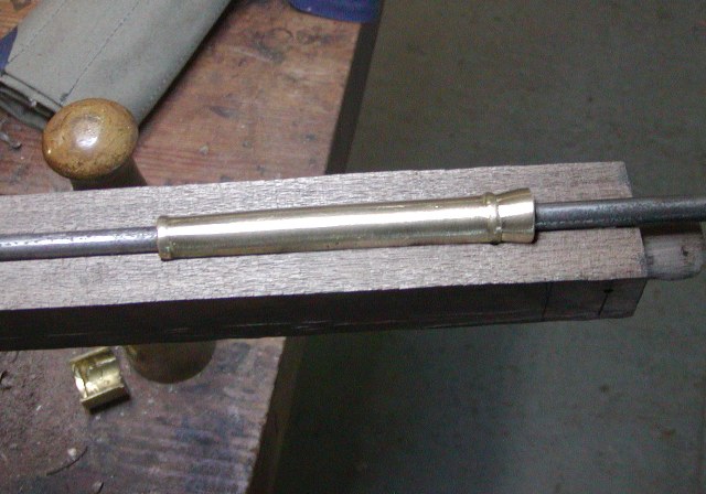
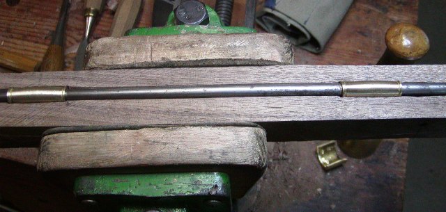
Make sure the second pipe is just behind the forward sling swivel bolt so the swivel rest on it.
dave
Let's shift to the ramrod pipes. The short land muskets have 4, a long trumpet forward pipe, 2 short middle pipes, and a rear pipe. The long front pipe is 4 1/8" long and the mouth of the pipe is 1 7/8" from the forend of the stock. The front of the second pipe is 3 1/4" from the rear of the front pipe. It is 1 3/8" long and the rear of the pipe is 5 7/8" from the front of the third pipe. The third pipe is identical to the second and its rear is 5 3/4" from the front of the rear pipe. The rear pipe has a barrel 1 5/16" long attached to a tang 3 3/16" long. The rear pipe also has a rod retaining spring attached to the back of the tube. The forward pipes are not hard to inlet but the rear is a challenge. Be aware the tabs can show in the barrel channel so cut slots for them right through. The rear pipe has a tooth on the end of the tang that is supposed to anchor the rear of tang down in the wood. My experience is that the tangs are thick brass and don't need the spur to hold in place. I usually grind them off, which simplifies inletting a lot.
When you inlet the rear pipe, understand that the pipe widens to the rear. Don't try and inlet it so the barrel of the pipe is parallel with the ramrod. It flares toward the rear making it look like the pipe is inlet leaning forward.
The trumpet forward pipe and middle barrel pipes are easy to inlet using a couple of gouges and a stab in chisel.
Make sure the second pipe is just behind the forward sling swivel bolt so the swivel rest on it.
dave
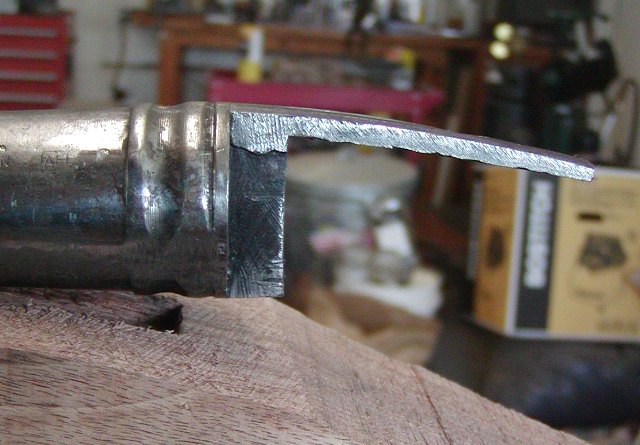
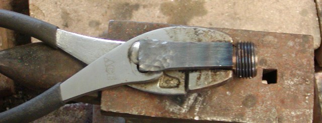
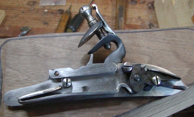
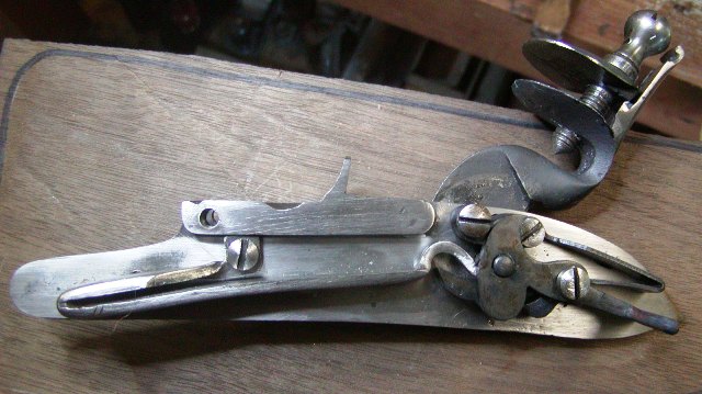
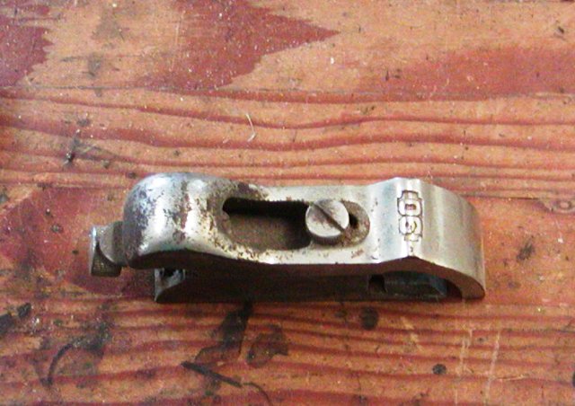
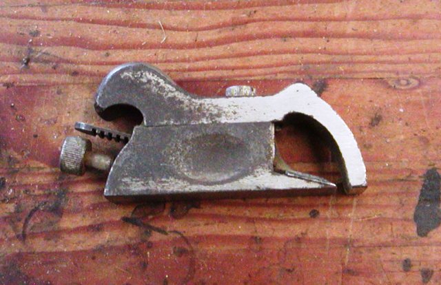
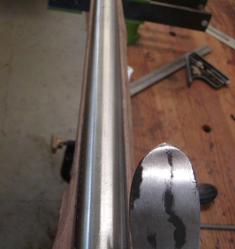
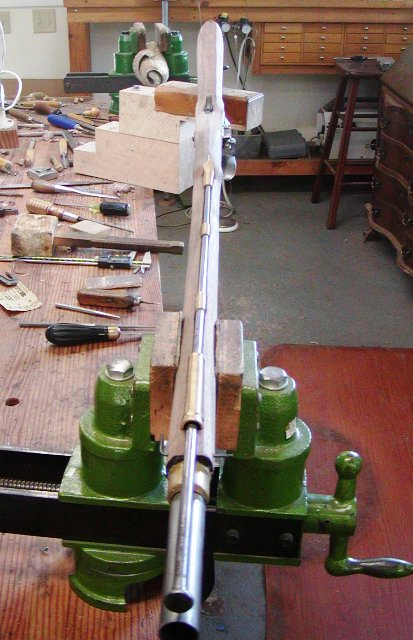
I love hand-made tools.Hi Bob,
Here are pictures of our barrel plane.
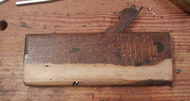
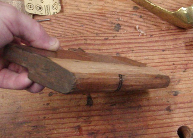
It is a handy tool but has to be razor sharp.
dave
- Joined
- Nov 26, 2005
- Messages
- 5,019
- Reaction score
- 9,973
Hi,
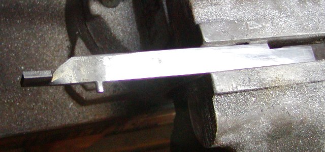
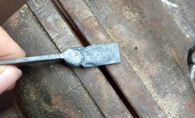
This next post is about making a proper mainspring. All the mainsprings on repro Besses are crudely made and barely functional. They are usually way too strong and unbalanced. We are fitting Miroku internal parts to a historically accurate lock plate, flint cock, and frizzen by TRS. The Miroku plate, frizzen, and flint cock are too small and have badly designed cast in engraving and stamping. However, the internal parts are mostly very high quality with 2 exceptions, the mainspring and the design of the tumbler. We used the mainspring to fix a different Miroku lock for a reenactor and needed to make a historically correct one for this current project. This is how we do it. We start with 1/8" thick 1075 steel, coat it with Dykem blue, and draw the pattern on it.
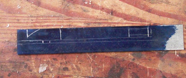
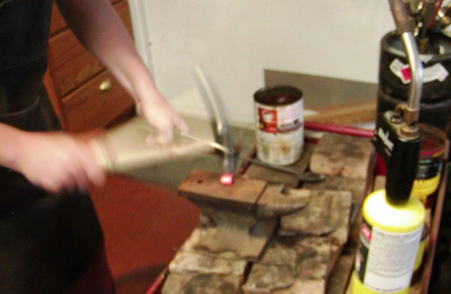
You can see the section that will become the tab on the left, the body of the spring, and the narrower section to become the hook on the right. You can also see where we leave metal to form the stud and where the main bend will be. Next is the arduous task of sawing out the pattern with a hacksaw. Once the spring is cut out the spring is held in a vise and the neck heated red hot with a Mapp gas torch. It is then turned 90 degrees to the spring leaves.
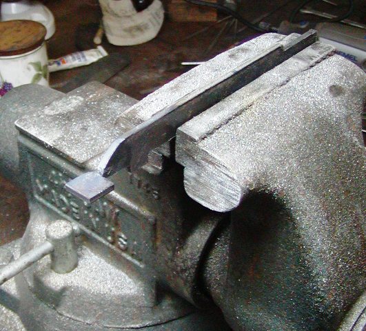
That forms the tab that butts under the lockplate bolster and is anchored with a screw. We file away excess metal on the tab on around the neck and form the stud. We aso clean up the spring on both sides. It is wise to polish up the steel a bit before bending because it is so much easier with the spring flat.
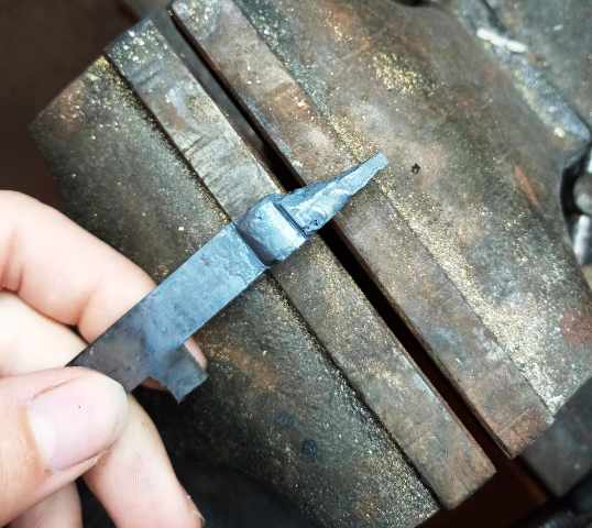
We file a very light line across the spring that marks the middle of the main bend on the outside. We hold the spring in our vise, heat it red hot just at that mark and hammer the steel over to make a bend a bit more than 90 degrees. We take the spring over to the anvil, heat the bend and hammer the bend almost closed. Then we hold the spring again in the vise, heat where the hook begins and bend it up almost 90 degrees.
We let it cool down and then heat the middle of the section to become the hook and bend it down with pliers. As we bend it down, we move the heat closer to the toe of the hook. The hook is left longer than needed so we can fit the spring on the lock. I drill the stud hole in the lock plate and place the spring on the lock to see how much the hook needs to be shortened. I cut a bit off, test the fit, and then cut or grind a little more off if needed. I want the hook to fully overlap the toe of the tumbler when the lock is at rest. Then I want the toe to slide almost all the way up the tumbler foot when the lock is pulled to half cock. Finally, I want the toe of the hook solidly positioned in the instep of the tumbler when the cock is pulled to full. With the toe of the hook in the instep, as the cock is pulled back to full, the tumbler rotates around the end of the spring somewhat rather than just pushing it up. That provides a little bit of "let off" of spring tension as the lock is cocked. Once fitted, we clean up the spring. Grinding the main bend smooth gets rid of our transverse mark and we file the hook into a smooth shape as well as thin the bottom of the spring as it approaches the hook. After that, I filed in some detailing found on the original springs including production marks near the bend. I drill the hole for the anchor screw and prepare the spring for heat treating. I usually open the main bend a little heating it red hot and give the lower leaf a slight downward arc.
I have learned a lot about heat treating steel from Wick Ellerbe (our own LRB). When he writes about metals, I read it and store away the knowledge. He recommeded using salt brine for quenching because 1075 steel has to be cooled very quickly for hardening. I previously used canola oil but used brine for this spring. It worked great. We heated the spring bright red with two Mapp torches and then quenched in brine that was at about 130 degrees. Then we polished off any scale or discoloring, and tempered the spring in my electric oven at 750 degrees for 1 hour. We let it air cool and tested it in the lock. It worked great. It has the right tension and slightly whippy feel of the originals.
I drilled and tapped the lock plate for the mainspring screw. Keep in mind, the screw is somewaht redundant. The tab on the spring should butt against the bottom of the lock plate bolster solidly such that the springs works without the screw. The screw simply keeps the spring tight against the lock plate. The photos below show the positions of the hook on the tumbler as the cock is drawn back from rest, half, and full cock.
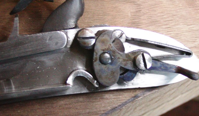
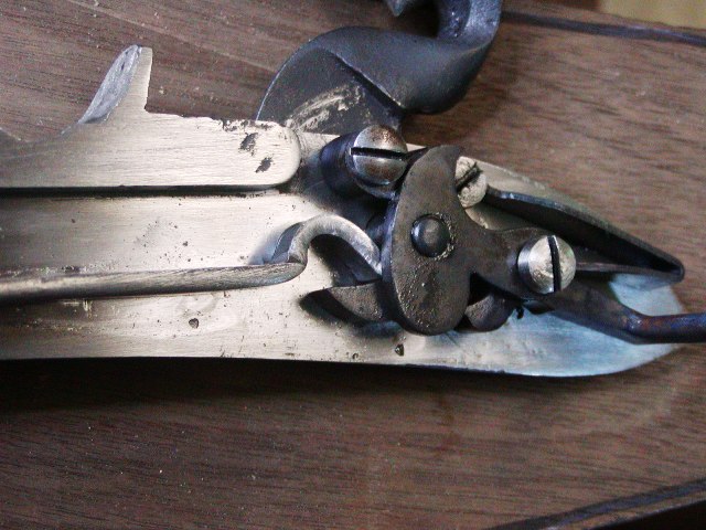
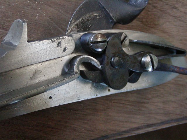
Notice at full cock, the lower leaf of the spring is almost straight with no upward bend in the middle.
If you have a copy of Goldstein and Mowbray's "Brown Bess", look at photos of original springs and then ours. We are pretty close. In the next post, I will describe making the lock.
dave
This next post is about making a proper mainspring. All the mainsprings on repro Besses are crudely made and barely functional. They are usually way too strong and unbalanced. We are fitting Miroku internal parts to a historically accurate lock plate, flint cock, and frizzen by TRS. The Miroku plate, frizzen, and flint cock are too small and have badly designed cast in engraving and stamping. However, the internal parts are mostly very high quality with 2 exceptions, the mainspring and the design of the tumbler. We used the mainspring to fix a different Miroku lock for a reenactor and needed to make a historically correct one for this current project. This is how we do it. We start with 1/8" thick 1075 steel, coat it with Dykem blue, and draw the pattern on it.
You can see the section that will become the tab on the left, the body of the spring, and the narrower section to become the hook on the right. You can also see where we leave metal to form the stud and where the main bend will be. Next is the arduous task of sawing out the pattern with a hacksaw. Once the spring is cut out the spring is held in a vise and the neck heated red hot with a Mapp gas torch. It is then turned 90 degrees to the spring leaves.
That forms the tab that butts under the lockplate bolster and is anchored with a screw. We file away excess metal on the tab on around the neck and form the stud. We aso clean up the spring on both sides. It is wise to polish up the steel a bit before bending because it is so much easier with the spring flat.
We file a very light line across the spring that marks the middle of the main bend on the outside. We hold the spring in our vise, heat it red hot just at that mark and hammer the steel over to make a bend a bit more than 90 degrees. We take the spring over to the anvil, heat the bend and hammer the bend almost closed. Then we hold the spring again in the vise, heat where the hook begins and bend it up almost 90 degrees.
We let it cool down and then heat the middle of the section to become the hook and bend it down with pliers. As we bend it down, we move the heat closer to the toe of the hook. The hook is left longer than needed so we can fit the spring on the lock. I drill the stud hole in the lock plate and place the spring on the lock to see how much the hook needs to be shortened. I cut a bit off, test the fit, and then cut or grind a little more off if needed. I want the hook to fully overlap the toe of the tumbler when the lock is at rest. Then I want the toe to slide almost all the way up the tumbler foot when the lock is pulled to half cock. Finally, I want the toe of the hook solidly positioned in the instep of the tumbler when the cock is pulled to full. With the toe of the hook in the instep, as the cock is pulled back to full, the tumbler rotates around the end of the spring somewhat rather than just pushing it up. That provides a little bit of "let off" of spring tension as the lock is cocked. Once fitted, we clean up the spring. Grinding the main bend smooth gets rid of our transverse mark and we file the hook into a smooth shape as well as thin the bottom of the spring as it approaches the hook. After that, I filed in some detailing found on the original springs including production marks near the bend. I drill the hole for the anchor screw and prepare the spring for heat treating. I usually open the main bend a little heating it red hot and give the lower leaf a slight downward arc.
I have learned a lot about heat treating steel from Wick Ellerbe (our own LRB). When he writes about metals, I read it and store away the knowledge. He recommeded using salt brine for quenching because 1075 steel has to be cooled very quickly for hardening. I previously used canola oil but used brine for this spring. It worked great. We heated the spring bright red with two Mapp torches and then quenched in brine that was at about 130 degrees. Then we polished off any scale or discoloring, and tempered the spring in my electric oven at 750 degrees for 1 hour. We let it air cool and tested it in the lock. It worked great. It has the right tension and slightly whippy feel of the originals.
I drilled and tapped the lock plate for the mainspring screw. Keep in mind, the screw is somewaht redundant. The tab on the spring should butt against the bottom of the lock plate bolster solidly such that the springs works without the screw. The screw simply keeps the spring tight against the lock plate. The photos below show the positions of the hook on the tumbler as the cock is drawn back from rest, half, and full cock.
Notice at full cock, the lower leaf of the spring is almost straight with no upward bend in the middle.
If you have a copy of Goldstein and Mowbray's "Brown Bess", look at photos of original springs and then ours. We are pretty close. In the next post, I will describe making the lock.
dave
Last edited:
- Joined
- Nov 1, 2018
- Messages
- 3,224
- Reaction score
- 2,285
Hi,
This next post is about making a proper mainspring. All the mainsprings on repro Besses are crudely made and barely functional. They are usually way too strong and unbalanced. We are fitting Miroku internal parts to a historically accurate lock plate, flint cock, and frizzen by TRS. The Miroku plate, frizzen, and flint cock are too small and have badly designed cast in engraving and stamping. However, the internal parts are mostly very high quality with 2 exceptions, the mainspring and the design of the tumbler. We used the mainspring to fix a different Miroku lock for a reenactor and needed to make a historically correct one for this current project. This is how we do it. We start with 1/8" thick 1075 steel, coat it with Dykem blue, and draw the pattern on it.
You can see the section that will become the tab on the left, the body of the spring, and the narrower section to become the hook on the right. You can also see where we leave metal to form the stud and where the main bend will be. Next is the arduous task of sawing out the pattern with a hacksaw. Once the spring is cut out the spring is held in a vise and the neck heated red hot with a Mapp gas torch. It is then turned 90 degrees to the spring leaves.
That forms the tab that butts under the lockplate bolster and is anchored with a screw. We file away excess metal on the tab on around the neck and form the stud. We aso clean up the spring on both sides. It is wise to polish up the steel a bit before bending because it is so much easier with the spring flat.
We file a very light line across the spring that marks the middle of the main bend on the outside. We hold the spring in our vise, heat it red hot just at that mark and hammer the steel over to make a bend a bit more than 90 degrees. We take the spring over to the anvil, heat the bend and hammer the bend almost closed. Then we hold the spring again in the vise, heat where the hook begins and bend it up almost 90 degrees.
We let it cool down and then heat the middle of the section to become the hook and bend it down with pliers. As we bend it down, we move the heat closer to the toe of the hook. The hook is left longer than needed so we can fit the spring on the lock. I drill the stud hole in the lock plate and place the spring on the lock to see how much the hook needs to be shortened. I cut a bit off, test the fit, and then cut or grind a little more off if needed. I want the hook to fully overlap the toe of the tumbler when the lock is at rest. Then I want the toe to slide almost all the way up the tumbler foot when the lock is pulled to half cock. Finally, I want the toe of the hook solidly positioned in the instep of the tumbler when the cock is pulled to full. With the toe of the hook in the instep, as the cock is pulled back to full, the tumbler rotates around the end of the spring somewhat rather than just pushing it up. That provides a little bit of "let off" of spring tension as the lock is cocked. Once fitted, we clean up the spring. Grinding the main bend smooth gets rid of our transverse mark and we file the hook into a smooth shape as well as thin the bottom of the spring as it approaches the hook. After that, I filed in some detailing found on the original springs including production marks near the bend. I drill the hole for the anchor screw and prepare the spring for heat treating. I usually open the main bend a little heating it red hot and give the lower leaf a slight downward arc.
I have learned a lot about heat treating steel from Wick Ellerbe (our own LRB). When he writes about metals, I read it and store away the knowledge. He recommeded using salt brine for quenching because 1075 steel has to be cooled very quickly for hardening. I previously used canola oil but used brine for this spring. It worked great. We heated the spring bright red with two Mapp torches and then quenched in brine that was at about 130 degrees. Then we polished off any scale or discoloring, and tempered the spring in my electric oven at 750 degrees for 1 hour. We let it air cool and tested it in the lock. It worked great. It has the right tension and slightly whippy feel of the originals.
I drilled and tapped the lock plate for the mainspring screw. Keep in mind, the screw is somewaht redundant. The tab on the spring should butt against the bottom of the lock plate bolster solidly such that the springs works without the screw. The screw simply keeps the spring tight against the lock plate. The photos below show the positions of the hook on the tumbler as the cock is drawn back from rest, half, and full cock.
Notice at full cock, the lower leaf of the spring is almost straight with no upward bend in the middle.
If you have a copy of Goldstein and Mowbray's "Brown Bess", look at photos of original springs and then ours. We are pretty close. In the next post, I will describe making the lock.
dave
Hi Dave
Were the original bess springs over sized because of the lack of quality spring steel?
The casted springs by the rifle shoppe appear to have a sort of taper in terms of thickness from end to end that can only be achieved with a very heavy steel blank.
It also appears to be the case on the frizzen and sear spring.
Was the flat bar filed to a tapered finish before shaping or was the shaped spring to a taper?
Last edited:
- Joined
- Nov 26, 2005
- Messages
- 5,019
- Reaction score
- 9,973
Hi Nick,
The lower leaf of the spring is tapered toward the hook both in width and thickness. That could have been done either before the spring was bent or after. The section to form the hook is better thinned a bit before bending the hook. But not much. The taper in thickness is not big so the spring remains very strong. Moreover, very strong throughout its range of motion. It should be pushing the tumbler down very hard when the flint cock is at rest.
dave
- Joined
- Nov 26, 2005
- Messages
- 5,019
- Reaction score
- 9,973
Hi,
We used a TRS lock plate, flint cock, and frizzen but mostly Miroku internal parts to build out first lock for the short land musket. This lock will be marked "TOWER" and will be a pattern 1756 style with the long sear spring. That means there is no second screw hole showing behind the flint cock. Moreover the top jaw screw only has a slot and no hole. After cleaning up the cast parts, we drilled the tumbler hole a little undersized using the witness mark on the TRS casting. That is the last witness mark we will use. We used a round stone to open the hole enough for a tight fit of the tumbler, and then used 600 grit rubbing compound to lap the tumbler into the plate. The Miroku tumbler has some design issues to be corrected. It is a fine casting and of excellent steel but the the height of the lip of the half cock notch is more than that of the full cock notch when measured from the center of the spindle that fits in the bridle. What that means is unless the trigger has a very heavy pull, keeping the sear far away from the tumbler during firing, the lock will catch at half cock when fired. Moreover the distance of the full cock notch behind the half cock notch requires the cock to be pulled back too far. With the larger, historically correct flint cock. the elbow of the bend of the cock will hit the stock. So we anneal the tumbler and reshape it. The diagram below shows the changes. The dotted lines are the original profile.
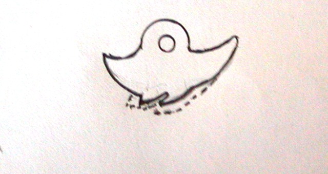
The changes I made allow the trigger pull to be much lighter and the flint cock has plenty of travel but does not hit the stock when pulled to full. The key is that the half cock notch is lower than the full cock notch so a light trigger pull can be arranged if desired.
The only witness marks we used on the TRS cast lock plate were those for the tumbler hole and the sear screw. All other marks were ignored. We made sure the tumbler was located so the flint cock just cleared but over hung the pan fence and the jaws were pointed toward the forward edge of the pan.
Then we drilled the sear screw hole so it went right through the center of its engraving on the lock plate. Those 2 references established all the others. One problem with the Miroku bridle is the hole for the sear screw is too large allowing the screw to wobble a bit. We fixed that by making a new screw with a wider shoulder for the hole in the bridle, a thinner shank to precisely fit the sear, and a shoulder on the threads so the screw tightens against the lock plate before pinching the sear.
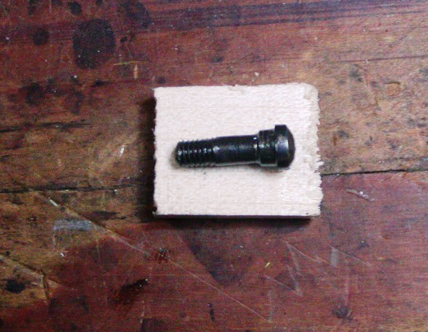
I do not have a milling machine. I did it all turning the screw in a drill chuck mounted in a wood lathe and files. After that, we drilled and fitted the bridle screw and pin, and then the sear spring and screw.

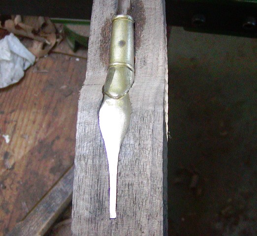
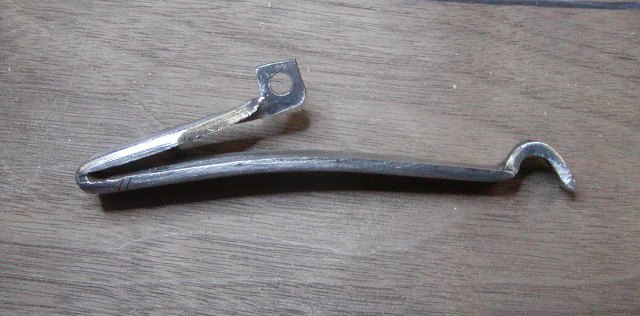
We fitted the cock on the tumblet post such that its shoulder came to rest on the lock plate exactly when the rear end of the tumbler struck the rear of the bridle. Original musket locks were not fitted that precisely but we could do it easily so we did. I made a new frizzen spring pivot screw and drilled the frizzen and lock plate. When you drill the hole through a frizzen, always place a paper tin shim under the back edge of the pan cover. That prevents the inevitable raising of the front of the pan cover when the clearance hole for the pivot screw is drilled and the screw installed. That almost always happens so use the shim. I posted previously about making the main spring but I also decided to make the feather spring from scatch. I just did not want to wait for the cast one from TRS. I used flat bar of 1075 steel and cut it out for the pin and to make the finial. To make the base for the finial, I cut about 1/2 way through the outside of the blank and about 1/8 through the inside edge of the blank. Then I heated that neck red hot and turned the base for the finial 90 degrees to the leaves of the spring. Then I welded steel on to that base to form the boss for the screw and finial.
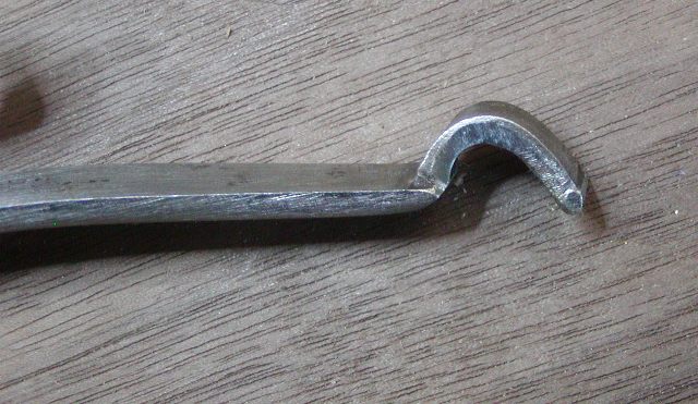
Then I thinned and filed the boss and finial to shape.
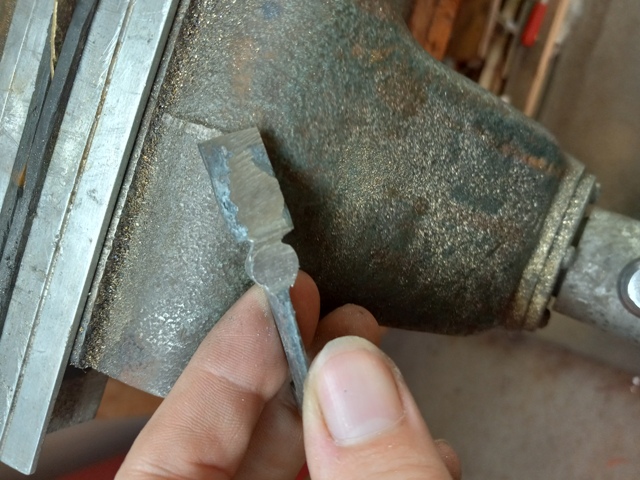
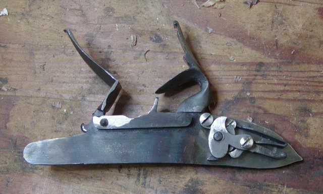
I driilled the boss for the screw, shaped the finial, and then bent the spring to fit the lock plate and frizzen. After fitting and cleaning up, I hardened and tempered the spring. Here is the result.
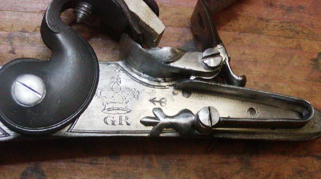
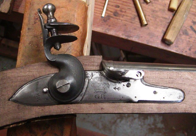
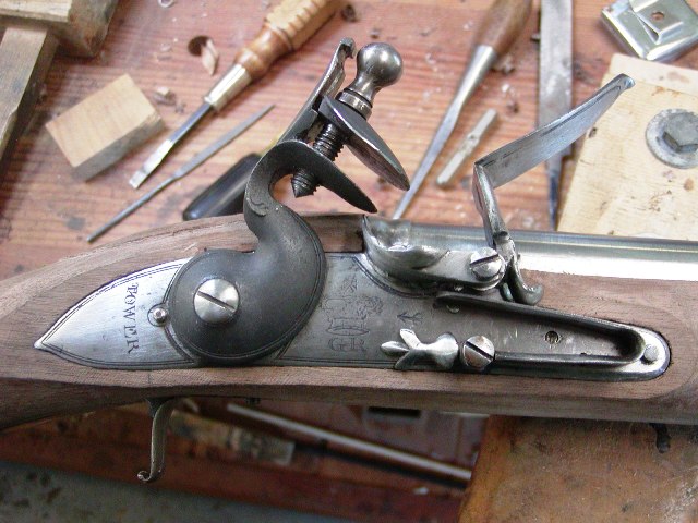
Here is the lock mostly assembled with spring and internals hardened and tempered but all else needing clean up and polishing before case hardening. Most of the engraving will be wiped away and I will engave it before hardening.
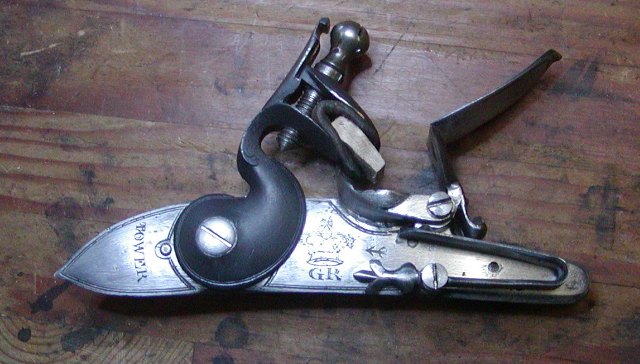
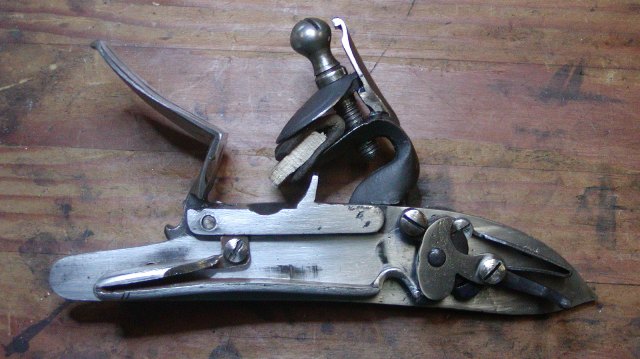
The lock functions superbly and I doubt I will need to adjust the springs further to tune the lock. Today was Maria's last day in the shop before going to Siena College. It was a bittersweet day but we had fun shooting my Wogden dueling pistols at a gong from 20 paces. The game was that I had a printed page with 3 columns each with classic Shakespearean insulting words and you had to compose and say an insult to the target using selections from each column.
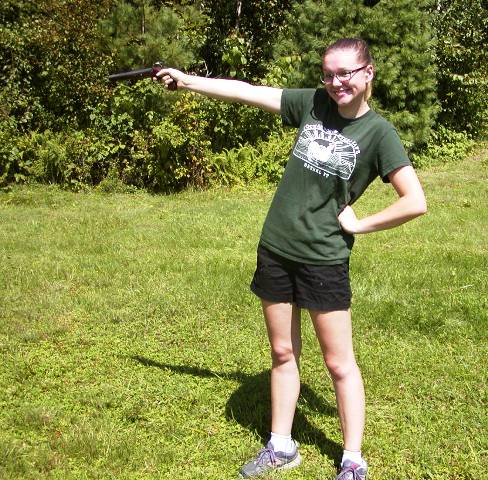
I think Maria's was "You frothy old codpiece!"
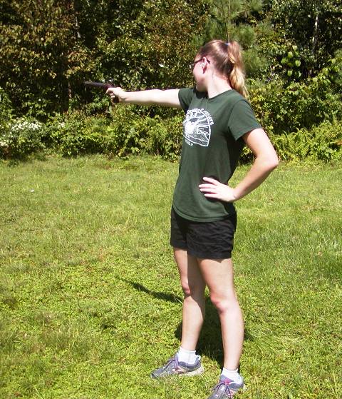
Aim and BOOM!
We had fun and I will miss her but she will come back on holidays and next summer to build mor guns. We also had a spectacular sunset, which I will share.


dave
We used a TRS lock plate, flint cock, and frizzen but mostly Miroku internal parts to build out first lock for the short land musket. This lock will be marked "TOWER" and will be a pattern 1756 style with the long sear spring. That means there is no second screw hole showing behind the flint cock. Moreover the top jaw screw only has a slot and no hole. After cleaning up the cast parts, we drilled the tumbler hole a little undersized using the witness mark on the TRS casting. That is the last witness mark we will use. We used a round stone to open the hole enough for a tight fit of the tumbler, and then used 600 grit rubbing compound to lap the tumbler into the plate. The Miroku tumbler has some design issues to be corrected. It is a fine casting and of excellent steel but the the height of the lip of the half cock notch is more than that of the full cock notch when measured from the center of the spindle that fits in the bridle. What that means is unless the trigger has a very heavy pull, keeping the sear far away from the tumbler during firing, the lock will catch at half cock when fired. Moreover the distance of the full cock notch behind the half cock notch requires the cock to be pulled back too far. With the larger, historically correct flint cock. the elbow of the bend of the cock will hit the stock. So we anneal the tumbler and reshape it. The diagram below shows the changes. The dotted lines are the original profile.
The changes I made allow the trigger pull to be much lighter and the flint cock has plenty of travel but does not hit the stock when pulled to full. The key is that the half cock notch is lower than the full cock notch so a light trigger pull can be arranged if desired.
The only witness marks we used on the TRS cast lock plate were those for the tumbler hole and the sear screw. All other marks were ignored. We made sure the tumbler was located so the flint cock just cleared but over hung the pan fence and the jaws were pointed toward the forward edge of the pan.
Then we drilled the sear screw hole so it went right through the center of its engraving on the lock plate. Those 2 references established all the others. One problem with the Miroku bridle is the hole for the sear screw is too large allowing the screw to wobble a bit. We fixed that by making a new screw with a wider shoulder for the hole in the bridle, a thinner shank to precisely fit the sear, and a shoulder on the threads so the screw tightens against the lock plate before pinching the sear.
I do not have a milling machine. I did it all turning the screw in a drill chuck mounted in a wood lathe and files. After that, we drilled and fitted the bridle screw and pin, and then the sear spring and screw.
We fitted the cock on the tumblet post such that its shoulder came to rest on the lock plate exactly when the rear end of the tumbler struck the rear of the bridle. Original musket locks were not fitted that precisely but we could do it easily so we did. I made a new frizzen spring pivot screw and drilled the frizzen and lock plate. When you drill the hole through a frizzen, always place a paper tin shim under the back edge of the pan cover. That prevents the inevitable raising of the front of the pan cover when the clearance hole for the pivot screw is drilled and the screw installed. That almost always happens so use the shim. I posted previously about making the main spring but I also decided to make the feather spring from scatch. I just did not want to wait for the cast one from TRS. I used flat bar of 1075 steel and cut it out for the pin and to make the finial. To make the base for the finial, I cut about 1/2 way through the outside of the blank and about 1/8 through the inside edge of the blank. Then I heated that neck red hot and turned the base for the finial 90 degrees to the leaves of the spring. Then I welded steel on to that base to form the boss for the screw and finial.
Then I thinned and filed the boss and finial to shape.
I driilled the boss for the screw, shaped the finial, and then bent the spring to fit the lock plate and frizzen. After fitting and cleaning up, I hardened and tempered the spring. Here is the result.
Here is the lock mostly assembled with spring and internals hardened and tempered but all else needing clean up and polishing before case hardening. Most of the engraving will be wiped away and I will engave it before hardening.
The lock functions superbly and I doubt I will need to adjust the springs further to tune the lock. Today was Maria's last day in the shop before going to Siena College. It was a bittersweet day but we had fun shooting my Wogden dueling pistols at a gong from 20 paces. The game was that I had a printed page with 3 columns each with classic Shakespearean insulting words and you had to compose and say an insult to the target using selections from each column.
I think Maria's was "You frothy old codpiece!"
Aim and BOOM!
We had fun and I will miss her but she will come back on holidays and next summer to build mor guns. We also had a spectacular sunset, which I will share.
dave
- Joined
- Nov 26, 2005
- Messages
- 5,019
- Reaction score
- 9,973
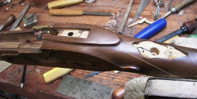
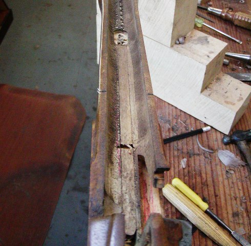
Hi,
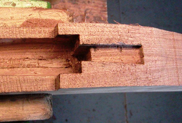
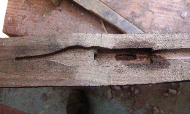
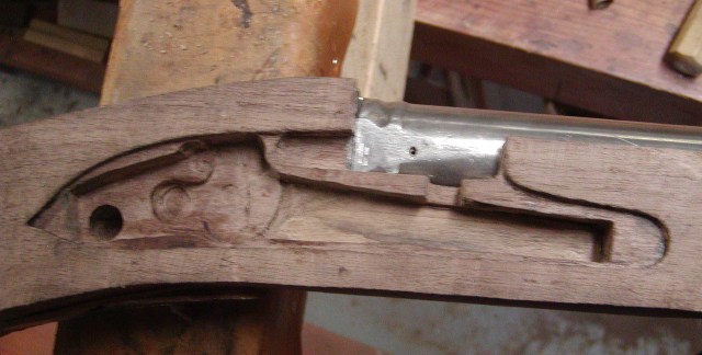
The lock was finished sufficiently to inlet. Our mortise is cut exactly like the original muskets. First we inlet the plate, then use a center-bore drill that fits into the tumble hole to mark the hole for the tumbler spindle. We place the tumble in that hole and trace around it. Then we cut out the wood within the tracing to the depth of the tumbler. Next we locate the bridle and sear screw holes using the lock plate and drill them to the proper depth.
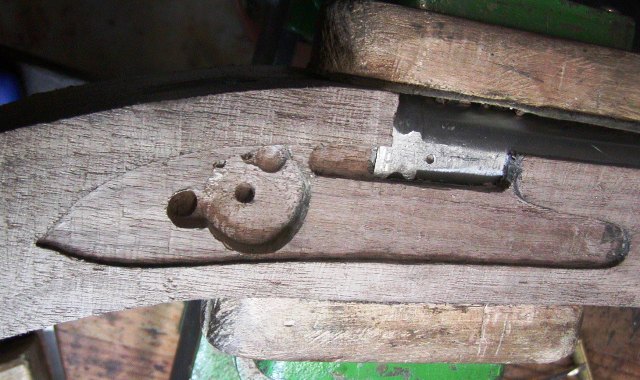
We put the screws in place in the mortise and put the bridle on top, tracing its outline. We cut out the wood for the bridle and then go on to drill the sear hole and inlet the sear and sear spring.
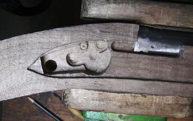
Finally, we use a 5/16" drill to make a series of holes the depth of the main spring, and clear away wood for that spring. We only remove as much wood as is needed to clear the parts.
dave
The lock was finished sufficiently to inlet. Our mortise is cut exactly like the original muskets. First we inlet the plate, then use a center-bore drill that fits into the tumble hole to mark the hole for the tumbler spindle. We place the tumble in that hole and trace around it. Then we cut out the wood within the tracing to the depth of the tumbler. Next we locate the bridle and sear screw holes using the lock plate and drill them to the proper depth.
We put the screws in place in the mortise and put the bridle on top, tracing its outline. We cut out the wood for the bridle and then go on to drill the sear hole and inlet the sear and sear spring.
Finally, we use a 5/16" drill to make a series of holes the depth of the main spring, and clear away wood for that spring. We only remove as much wood as is needed to clear the parts.
dave
- Joined
- Nov 26, 2005
- Messages
- 5,019
- Reaction score
- 9,973
Hi,
I got a lot done after Maria left for school. The gun is beginning to look like a King's musket. I am not going to show every step but focus on points specific to Brown Besses. We did not want to wait for TRS to ship a butt plate so we modified a long land pattern butt plate by Reeves Goerhing and turned it into a proper short land plate. Because these castings have shrunk over the years, we had to use a cross peen hammer to stretch the plate in several spots. It all worked out and we used Bailey's patterns as a guide.
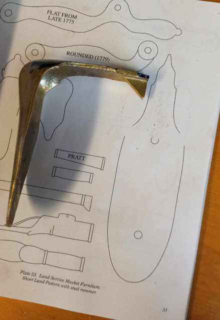
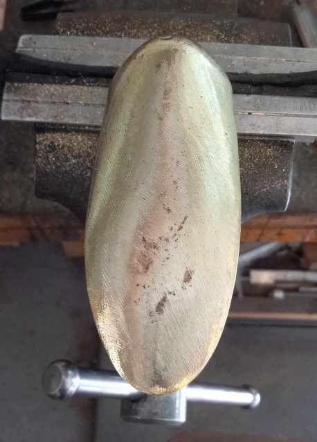
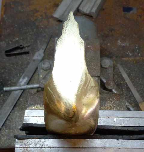
Then we inlet it and it worked fine. I've posted several threads showing how to inlet this style of butt plate so I am not going to to repeat that effort here again. Use the search function on this site to find those threads on building British muskets and fowlers.
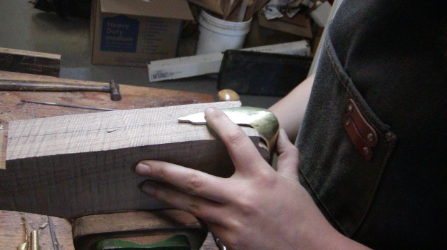
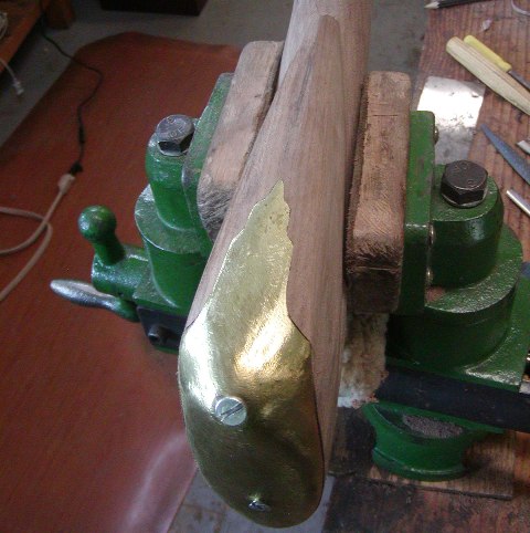
I will solder on a lug under the return for the cross pin a bit later. Here is a picture of the butt plate from a Miroku Bess and the Pedersoli is very similar.
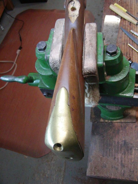
As you can see, it does not match the original shape very well.
dave
I got a lot done after Maria left for school. The gun is beginning to look like a King's musket. I am not going to show every step but focus on points specific to Brown Besses. We did not want to wait for TRS to ship a butt plate so we modified a long land pattern butt plate by Reeves Goerhing and turned it into a proper short land plate. Because these castings have shrunk over the years, we had to use a cross peen hammer to stretch the plate in several spots. It all worked out and we used Bailey's patterns as a guide.
Then we inlet it and it worked fine. I've posted several threads showing how to inlet this style of butt plate so I am not going to to repeat that effort here again. Use the search function on this site to find those threads on building British muskets and fowlers.
I will solder on a lug under the return for the cross pin a bit later. Here is a picture of the butt plate from a Miroku Bess and the Pedersoli is very similar.
As you can see, it does not match the original shape very well.
dave
- Joined
- Nov 26, 2005
- Messages
- 5,019
- Reaction score
- 9,973
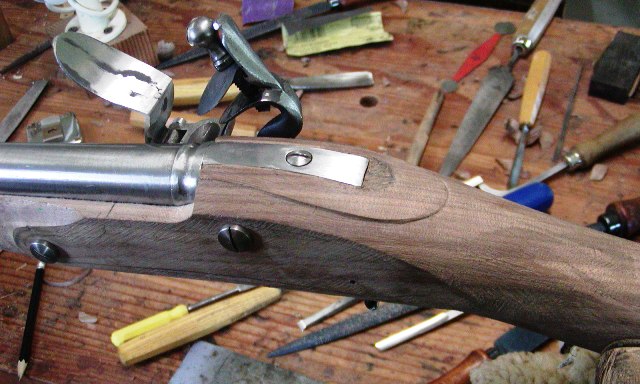
Hi,
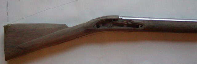
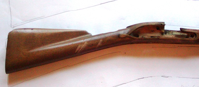
I shaped the butt stock and began final shaping of the wrist and lock areas. The baluster wrist, or hand rail, extends down the butt about halfway from the nose of the comb to the butt plate. It also tapers down just a little.
I chisel the bulk of the wood away using large gouges and shallow sweeps and then my pattern maker's rasps. My favorite for this job is my Liogier gunsmith's rasp, which is 12" long. I can rasp the whole length of the butt stock from the rear without rapping my knuckles on the butt plate. After shaping with rasps, I clean up the marks with this little Stanley #90 bull nose plane.
I can run the plane right down the crease of the wrist to straighten and clean it up. The wrist should be crisply and cleanly shaped and the hand rail portion fully rounded and not slab sided at all. The next photo shows butt stocks from this gun and a Miroku showing the immense difference it makes to the shape and proportions of the butt stock using a butt plate the right height.
These muskets are big through the lock and wrist sections. The width of the wrist behind the lock panel is at least 1 5/8" . That same measurement on my favorite early and robust PA long rifle is 1 7/16". The carved apron around the barrel tang is not an ugly tongue-like lump. Rather it is more finely shaped and given a convex profile. Here is a Miroku.
Here is what it is supposed to be.
Note the little half circle shaped flat at the end of the tang. This next photo shows the stock with a Miroku illustrating how the proportions of the accurate copy are so much more elegant than the Japanese repro. The same holds for the Pedersoli.
Our copy of the pattern 1769 has a fairly straight stock with only about 2" of drop at heel. I struggle to get my cheek down on it to aim but I usually need almost 3" of drop. The Italian and Japanese repros are even straighter and I cannot shoot them comfortably at all. The earler patterns tended to have more drop and are better shooters for those who actually have necks and are not built like bears or raccoons.
We fitted and pinned the trigger and the LOP is 13 5/8". Some of the originals have LOPs as long as 14". There is variation among originals but it was not to custom fit the soldier, rather just the variation caused by hand production. The owner is fairly short so the shorter LOP should fit him better. We shaved a lot of wood off the stock but a lot more will come off, particularly along the barrel.
Unlike all the repros,
these muskets were not bulky in front of the lock. They also do not have big wide lock panels. Those are thin and the flats are very thin. Ours currently looks like many of the repros but they will become very small soon.
We have almost everything in place except the thumb plate and the side plate. Those are up next and then final shaping.
dave
Man oh man Dave! Thank you for being on this forum!Hi,
I shaped the butt stock and began final shaping of the wrist and lock areas. The baluster wrist, or hand rail, extends down the butt about halfway from the nose of the comb to the butt plate. It also tapers down just a little.
I chisel the bulk of the wood away using large gouges and shallow sweeps and then my pattern maker's rasps. My favorite for this job is my Liogier gunsmith's rasp, which is 12" long. I can rasp the whole length of the butt stock from the rear without rapping my knuckles on the butt plate. After shaping with rasps, I clean up the marks with this little Stanley #90 bull nose plane.
I can run the plane right down the crease of the wrist to straighten and clean it up. The wrist should be crisply and cleanly shaped and the hand rail portion fully rounded and not slab sided at all. The next photo shows butt stocks from this gun and a Miroku showing the immense difference it makes to the shape and proportions of the butt stock using a butt plate the right height.
These muskets are big through the lock and wrist sections. The width of the wrist behind the lock panel is at least 1 5/8" . That same measurement on my favorite early and robust PA long rifle is 1 7/16". The carved apron around the barrel tang is not an ugly tongue-like lump. Rather it is more finely shaped and given a convex profile. Here is a Miroku.
Here is what it is supposed to be.
Note the little half circle shaped flat at the end of the tang. This next photo shows the stock with a Miroku illustrating how the proportions of the accurate copy are so much more elegant than the Japanese repro. The same holds for the Pedersoli.
Our copy of the pattern 1769 has a fairly straight stock with only about 2" of drop at heel. I struggle to get my cheek down on it to aim but I usually need almost 3" of drop. The Italian and Japanese repros are even straighter and I cannot shoot them comfortably at all. The earler patterns tended to have more drop and are better shooters for those who actually have necks and are not built like bears or raccoons.
We fitted and pinned the trigger and the LOP is 13 5/8". Some of the originals have LOPs as long as 14". There is variation among originals but it was not to custom fit the soldier, rather just the variation caused by hand production. The owner is fairly short so the shorter LOP should fit him better. We shaved a lot of wood off the stock but a lot more will come off, particularly along the barrel.
Unlike all the repros,
these muskets were not bulky in front of the lock. They also do not have big wide lock panels. Those are thin and the flats are very thin. Ours currently looks like many of the repros but they will become very small soon.
We have almost everything in place except the thumb plate and the side plate. Those are up next and then final shaping.
dave
Sam squanch
62 Cal.
- Joined
- Oct 9, 2019
- Messages
- 2,747
- Reaction score
- 3,764
Jim Kibler, I hope you have read this. Untapped market here….
Gorgeous work!
I still gotta get in line one of these days with a Potzdamn if I can get the parts out of TRS
I still gotta get in line one of these days with a Potzdamn if I can get the parts out of TRS
- Joined
- Nov 26, 2005
- Messages
- 5,019
- Reaction score
- 9,973
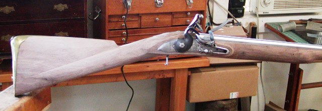
Hi Guys,
Thanks for looking and commenting! The musket is completely assembled waiting for final shaping and finishing. I had an appointment yesterday with the curator at Fort Ticonderoga to examine several original British muskets and carbines in their collection. Matt showed me an Elliot carbine, a Tower pattern 1769 short land musket, a Dublin Castle pattern 1769 shortland musket, and a pattern 1756 long land musket. These were all part of the huge Robert Nittolo collection, which the Fort bought last year. I was able to trace the stocks, take detailed measurements, and photos and add them to my existing library of original examples. I cannot post photos without permission from the Fort. I brought my short land project along to check its dimensions against the originals. It compared very well but in general was a tiny bit undersized. For example, the height of my stock at the breech is 2.1" whereas all of the original guns were at least 2.2" . The difference is caused by the repro barrel I am using which is 1.2" diameter at the breech. All of the originals were at least 1.4" (1 7/16"), almost 1/4" larger. They are also significantly larger at the muzzle. Anyway, I am doing pretty well adjusting for the differences and bringing the musket very close to original dimensions. Another difference is that all of the modern cast trigger guards from TOW or the Rifle Shoppe have bows that are significantly too small. It may be from shrinkage during the casting process. You can improve that by really thinning out the inside of the bows but not fix it entirely. The guards on Pedersoli, Miroku, and India-made Besses are even smaller and completely out of the range of the originals. Here is my stock compared with a tracing of a Tower pattern 1769 used by the 20th regiment of foot during the Rev War.
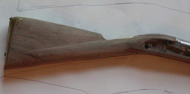
My stock is a little straighter but very close. The outline of the original includes the thickness of the trigger guard underneath.
Now I compare it with a Dublin Castle made pattern 1769 used by the 34th regiment.
I am pretty close to being right on the money. Here is a Miroku stock compared with the Tower musket.
It is much smaller and much straighter. Pedersolis are the same.
dave
Thanks for looking and commenting! The musket is completely assembled waiting for final shaping and finishing. I had an appointment yesterday with the curator at Fort Ticonderoga to examine several original British muskets and carbines in their collection. Matt showed me an Elliot carbine, a Tower pattern 1769 short land musket, a Dublin Castle pattern 1769 shortland musket, and a pattern 1756 long land musket. These were all part of the huge Robert Nittolo collection, which the Fort bought last year. I was able to trace the stocks, take detailed measurements, and photos and add them to my existing library of original examples. I cannot post photos without permission from the Fort. I brought my short land project along to check its dimensions against the originals. It compared very well but in general was a tiny bit undersized. For example, the height of my stock at the breech is 2.1" whereas all of the original guns were at least 2.2" . The difference is caused by the repro barrel I am using which is 1.2" diameter at the breech. All of the originals were at least 1.4" (1 7/16"), almost 1/4" larger. They are also significantly larger at the muzzle. Anyway, I am doing pretty well adjusting for the differences and bringing the musket very close to original dimensions. Another difference is that all of the modern cast trigger guards from TOW or the Rifle Shoppe have bows that are significantly too small. It may be from shrinkage during the casting process. You can improve that by really thinning out the inside of the bows but not fix it entirely. The guards on Pedersoli, Miroku, and India-made Besses are even smaller and completely out of the range of the originals. Here is my stock compared with a tracing of a Tower pattern 1769 used by the 20th regiment of foot during the Rev War.
My stock is a little straighter but very close. The outline of the original includes the thickness of the trigger guard underneath.
Now I compare it with a Dublin Castle made pattern 1769 used by the 34th regiment.
I am pretty close to being right on the money. Here is a Miroku stock compared with the Tower musket.
It is much smaller and much straighter. Pedersolis are the same.
dave
Similar threads
- Replies
- 77
- Views
- 4K
- Replies
- 4
- Views
- 304
- Replies
- 24
- Views
- 4K
