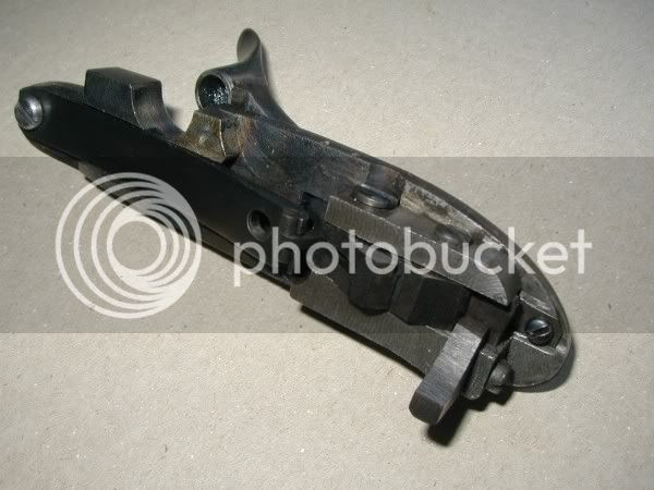
The other day I was surfing the web, trying to avoid doing anything productive, and I came across a neat little antique New York style mule ear rifle. What I found interesting was that the rifle was very similar in appearance to an antique rifle that I purchased a few years back, with the exception that mine has an A.W. Spies sidehammer on it. I always found the lines of this particular rifle appealing, but never went any further with it until I saw this mule ear. I started imagining what the original builder would have done if a customer had wanted a mule ear style rifle. I figured I would keep the basic elements the same and concentrate on building a lock that would fit the rest of the rifle, so off to the shop I went where I spent the better part of the afternoon avoiding the house chores that needed to be done. I figured some of your might like to see the progress on this project so I took a few pictures along the way.
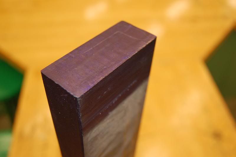
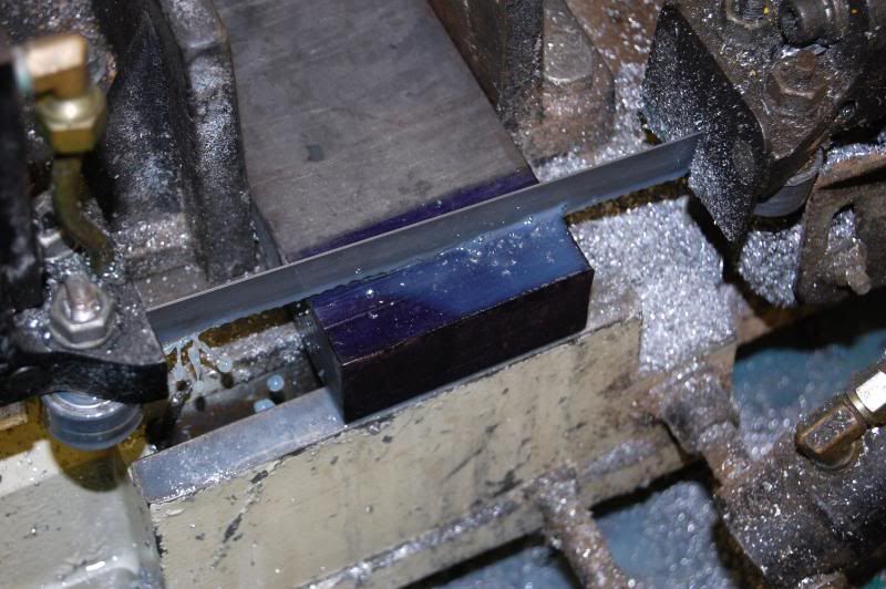
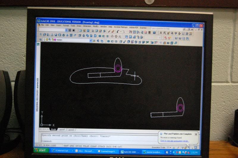
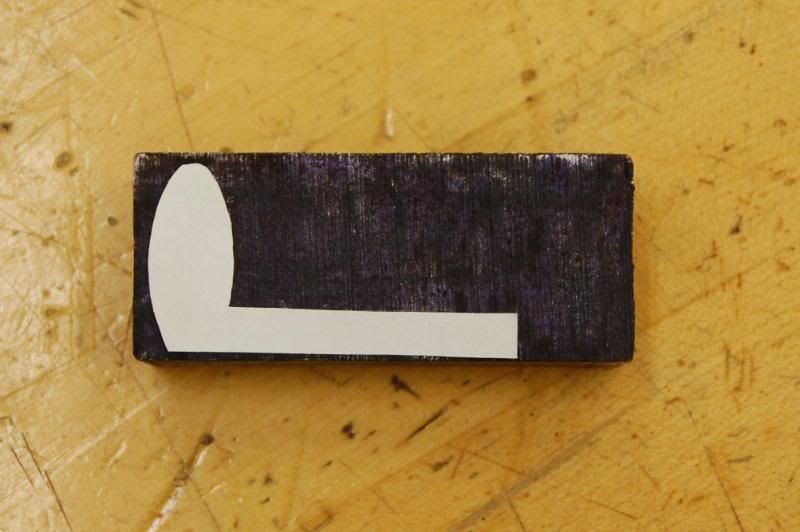
I started by tracing the original A.W. Spies lockplate on a piece of paper, scanning the image and importing it into AutoCAD where I played around with the location of the slot where the hammer will eventually go. I basically wanted to retain the original shape of the plate, but there are some significant changes to go to this style of lock. I started by grabbing a chunk of 3/8" (1/4" would have been better but I didn't have any) hot rolled steel and tracing the outline of the plate onto the end of the bar. The extra length of the bar gave me something to hold onto while I was cutting out the profile on the vertical bandsaw.
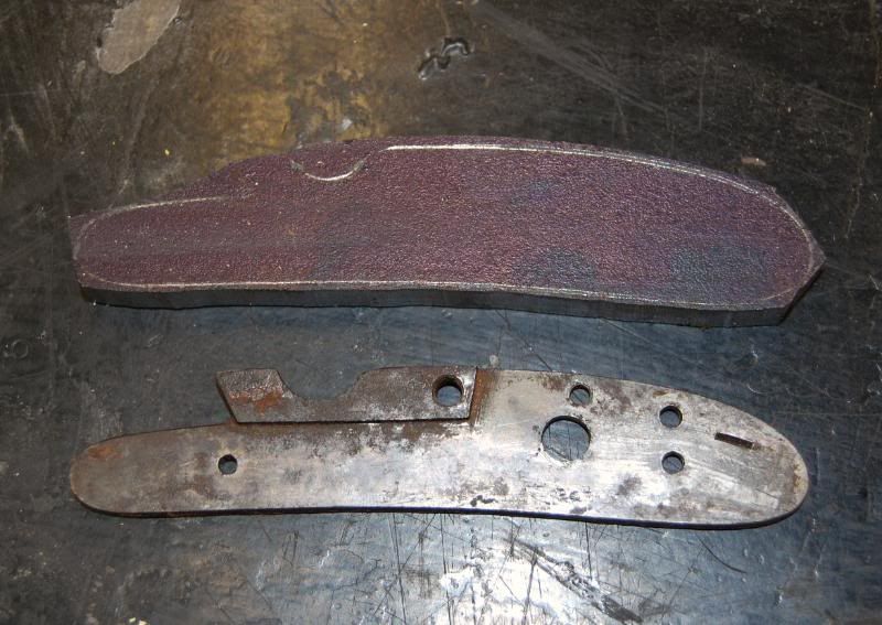
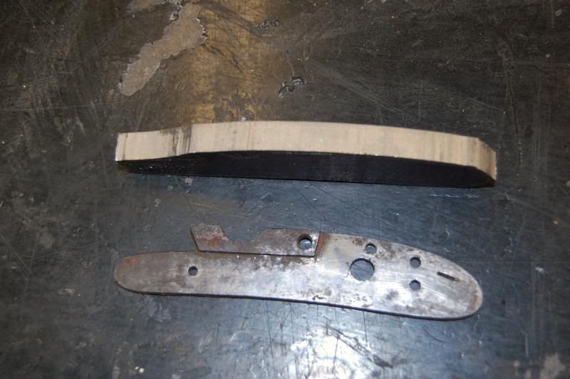
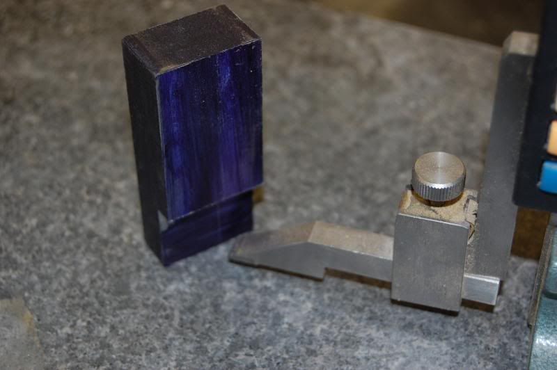
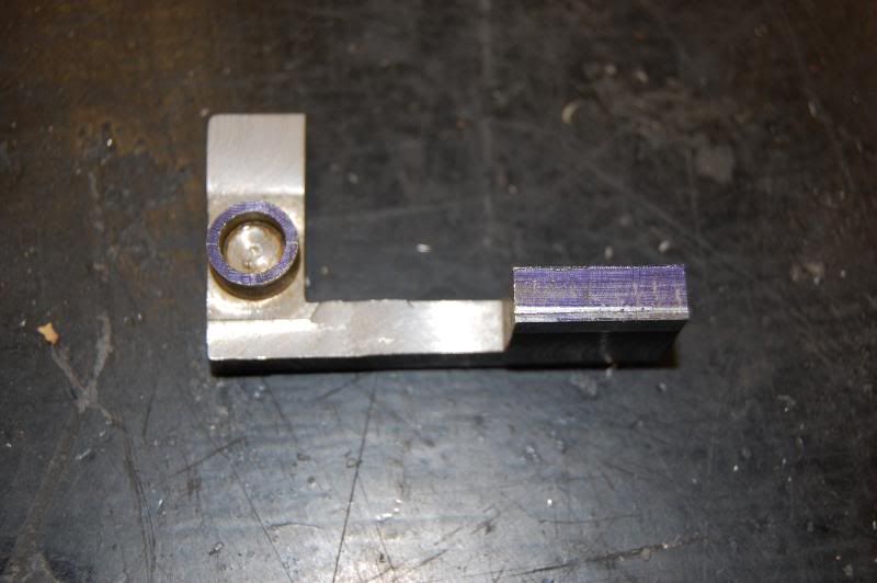
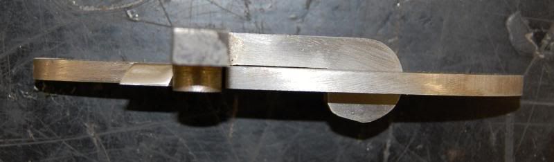
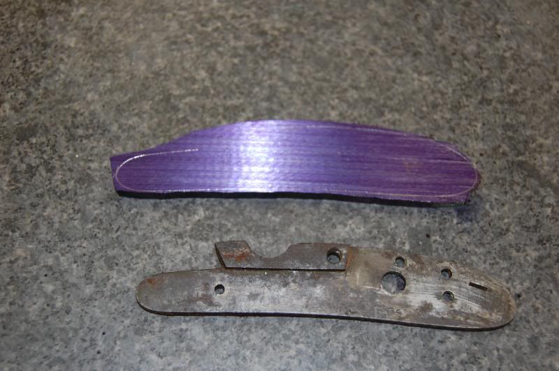
You could certainly use a hacksaw for this, but being essentially a lazy sort of person and having the technology I chose the easy route. You can see from the side view that there is a lot of material to remove.
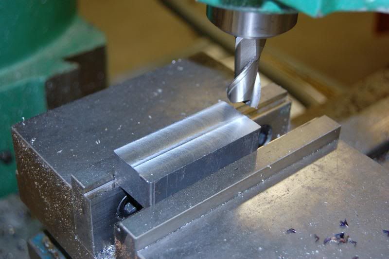
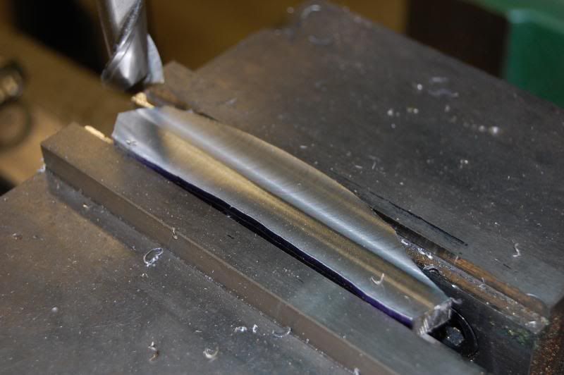
The rough blank was mounted into the vise of the mill and one side was surfaced.
With one face cleaned up a line was scribed into the edge at .206 and the other side was milled down to the line.
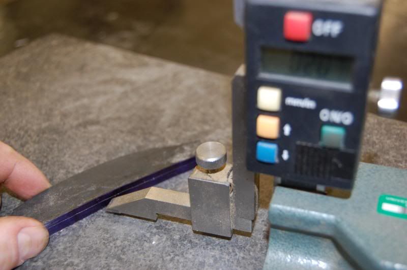
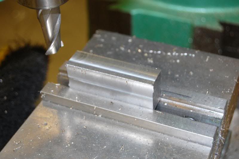
I than transferred the blank to the surface grinder where I ground both faces down to .195. This step wasn't really all that necessary, but I had the grinder available and it only took a couple of minutes to do.
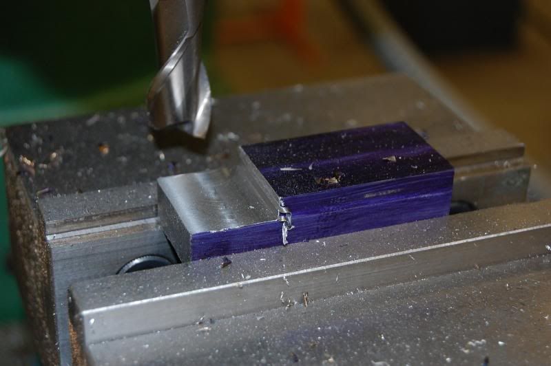
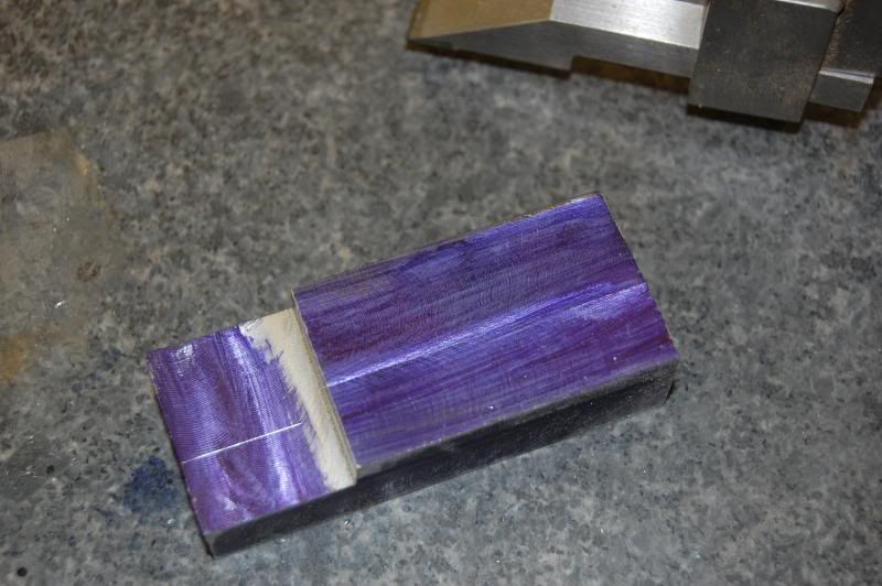
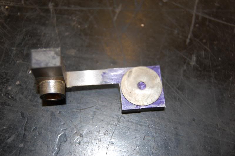
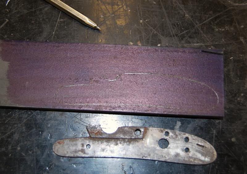
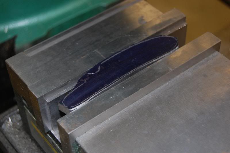
Following this the guidelines for the plate were re-traced using layout dye and the original plate as a template. I C-clamped it in place using a copper shim to protect the original.
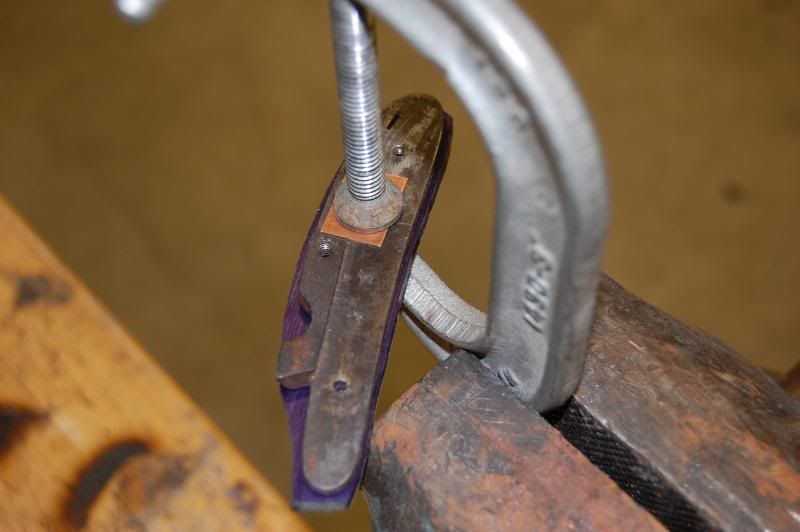
The new layout lines can be seen in the photo below.
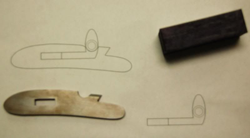
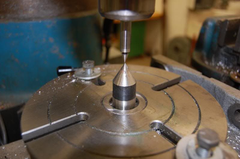
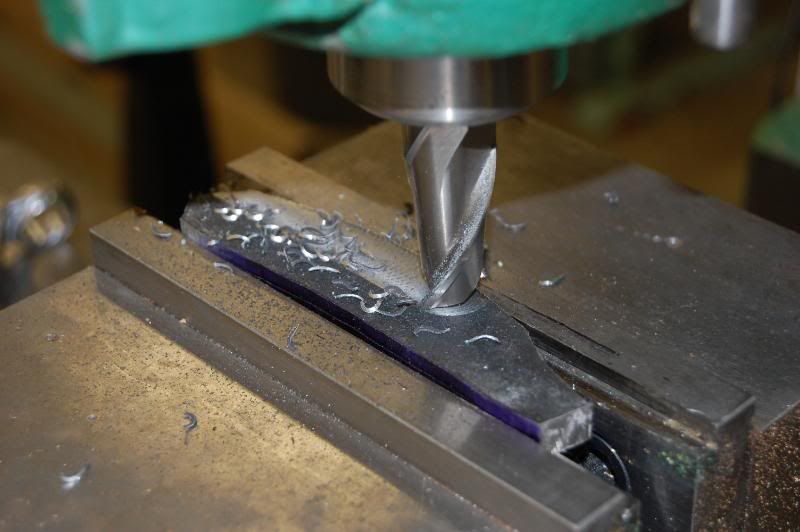
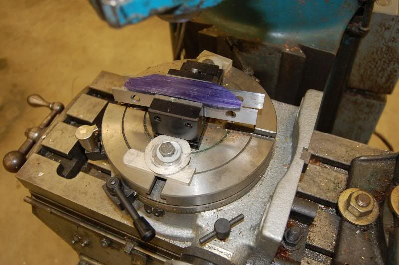
I felt it was best to cut the slot for the hammer next while the plate was still in the rough form. I chose to go this route since I didn't want to mash the edges of the finished plate in the mill. The slot was layed out using a print of the CAD drawing I created and scribed onto the blank using the boundry lines that were scribed onto the plate earlier. Since the slot does not run parallel to the edges of the plate I used a rotary table another mill to line up the slot parallel to the mills travel and adjusted it using an edge finder until I was satisfied.
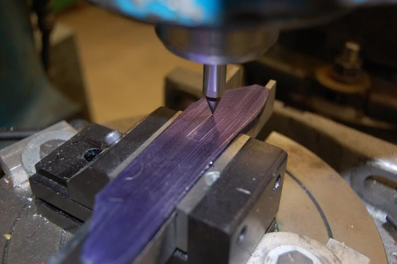
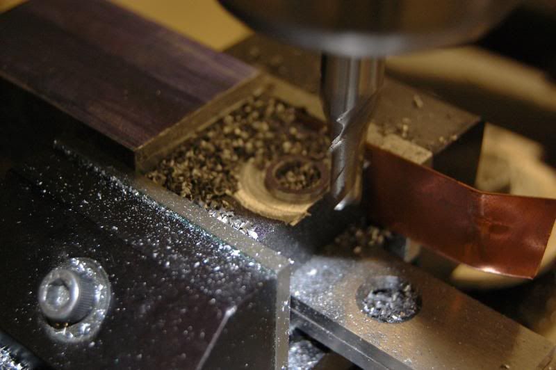
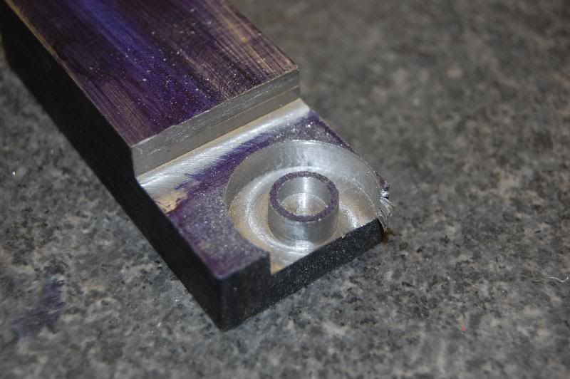
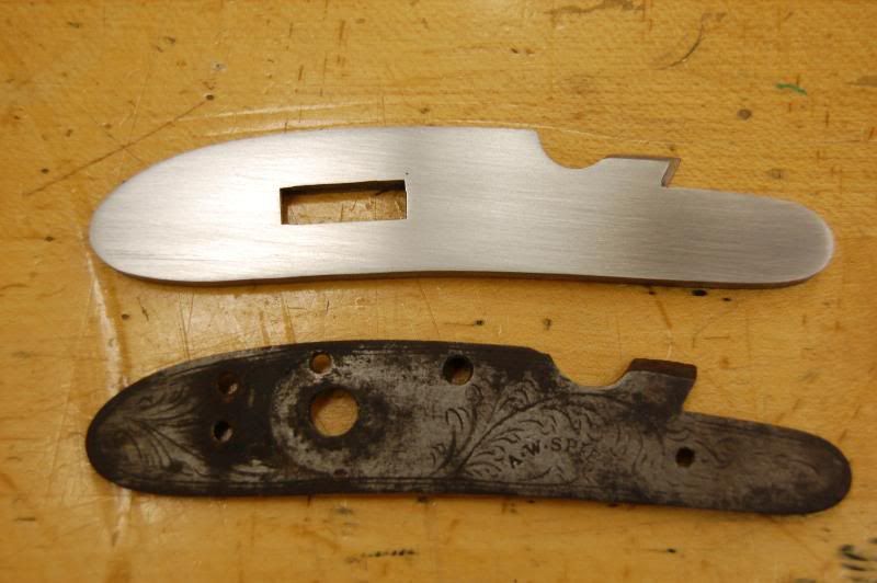
The slot was than cut using a 1/4" end mill and staying within the guidelines that were established.
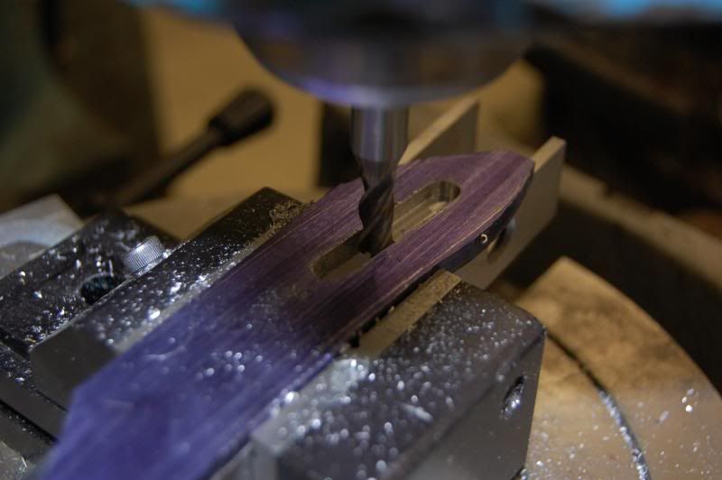
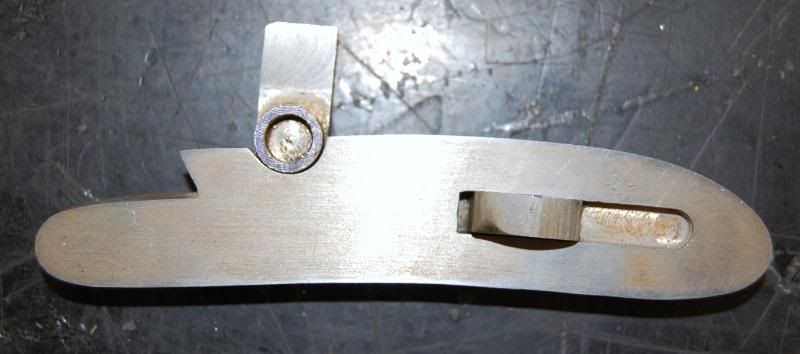
The forward part of the slot goes all the way through the plate; however, there is also a slot that goes only part of the way through the plate that is only visible from the inside. This is where the sear will fit in the finished lock.
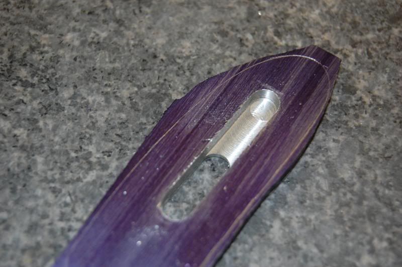
The 1/4" cutter leaves a radius that must be removed from the finished slot. I suppose a broach would be ideal for this step, but I chose to do it with a handfile that had one face ground safe. The edges of the slot look a bit fuzzy in the photos, but they are actually pretty clean, I'll do a bit more work on the slot when the hammer is being made.
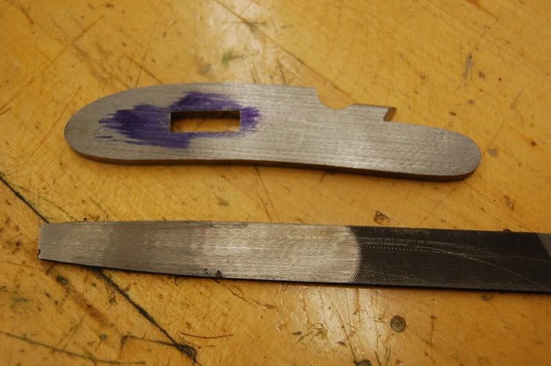
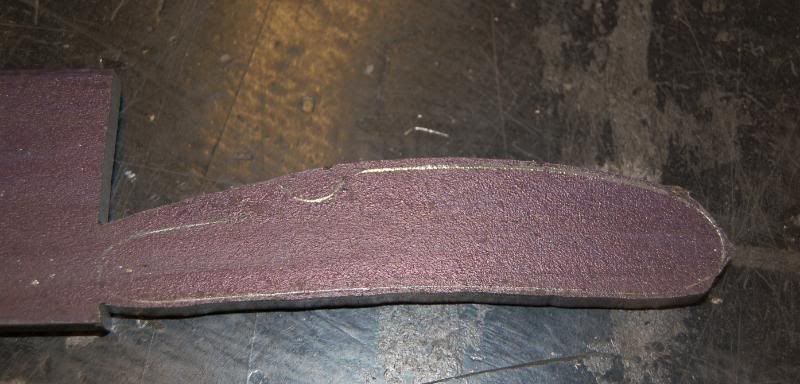
Following this step the plate was than filed and ground down to the outside guidelines established earlier. I set the table on my disk sander to 3 degrees to cut a slight draft on the plate to help with inletting in the future. Power tools are nice, but some jobs still need to be done by hand with a file which is what I used for the final finishing and shaping.
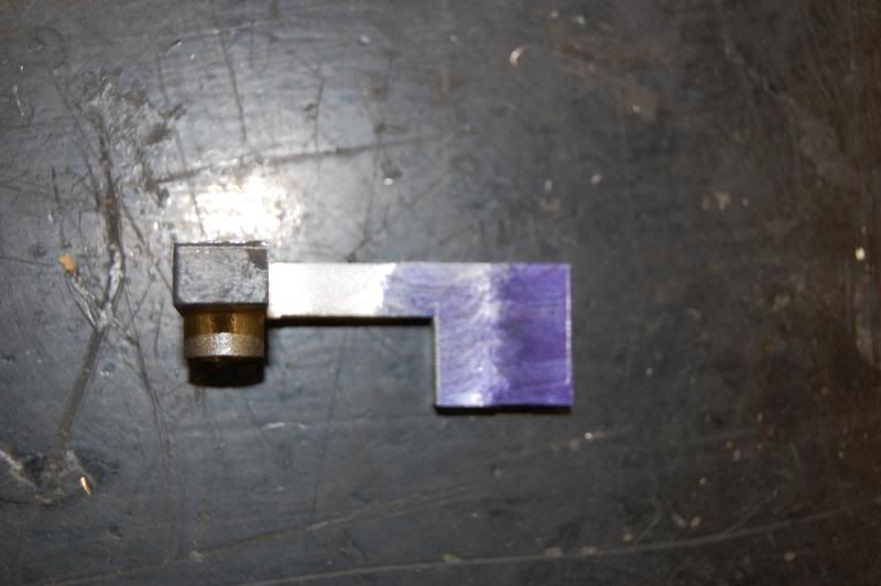
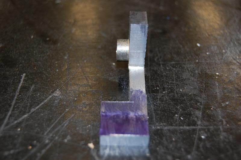
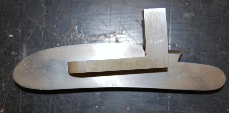
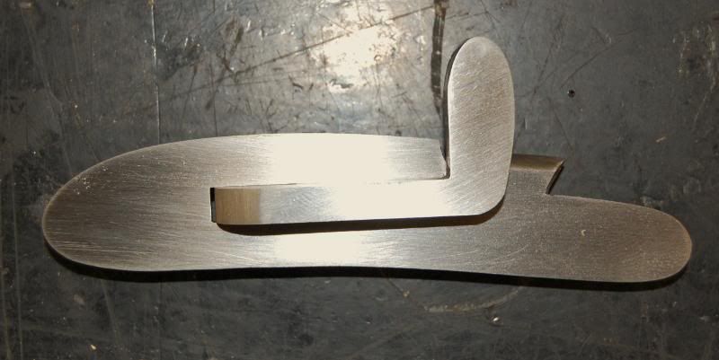
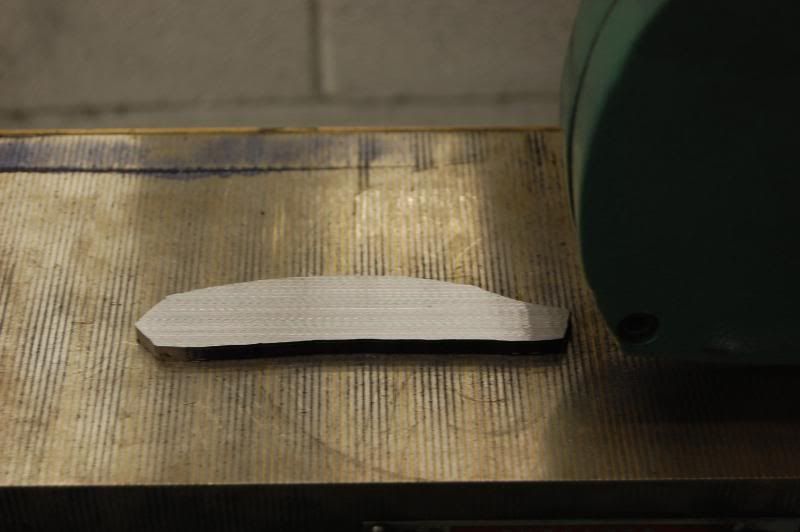
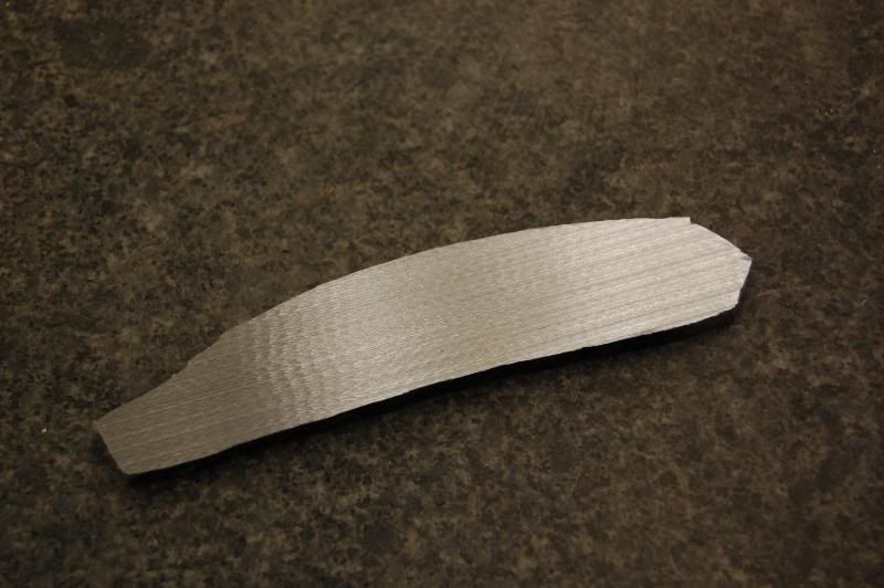
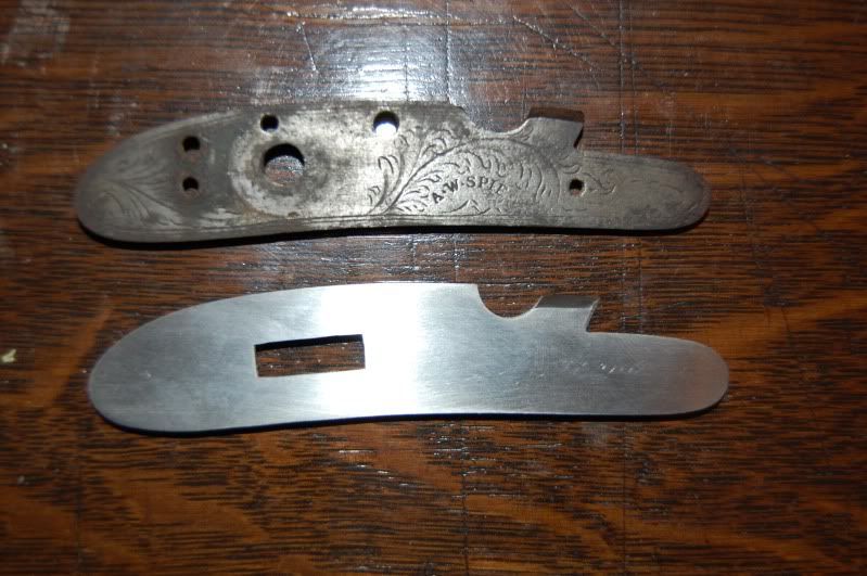
Here are a couple pictures of the plate as it is right now. The first photos were taken at a slight angle and the plate looks slightly different than the original, it is actually pretty close to the original shape; however, I will refine the forward part a bit more in the final finishing stage.
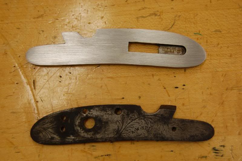
That is about as much as I plan on doing to the plate at this time. The next stage will be to make the hammer and sear.
I started by tracing the original A.W. Spies lockplate on a piece of paper, scanning the image and importing it into AutoCAD where I played around with the location of the slot where the hammer will eventually go. I basically wanted to retain the original shape of the plate, but there are some significant changes to go to this style of lock. I started by grabbing a chunk of 3/8" (1/4" would have been better but I didn't have any) hot rolled steel and tracing the outline of the plate onto the end of the bar. The extra length of the bar gave me something to hold onto while I was cutting out the profile on the vertical bandsaw.
You could certainly use a hacksaw for this, but being essentially a lazy sort of person and having the technology I chose the easy route. You can see from the side view that there is a lot of material to remove.
The rough blank was mounted into the vise of the mill and one side was surfaced.
With one face cleaned up a line was scribed into the edge at .206 and the other side was milled down to the line.
I than transferred the blank to the surface grinder where I ground both faces down to .195. This step wasn't really all that necessary, but I had the grinder available and it only took a couple of minutes to do.
Following this the guidelines for the plate were re-traced using layout dye and the original plate as a template. I C-clamped it in place using a copper shim to protect the original.
The new layout lines can be seen in the photo below.
I felt it was best to cut the slot for the hammer next while the plate was still in the rough form. I chose to go this route since I didn't want to mash the edges of the finished plate in the mill. The slot was layed out using a print of the CAD drawing I created and scribed onto the blank using the boundry lines that were scribed onto the plate earlier. Since the slot does not run parallel to the edges of the plate I used a rotary table another mill to line up the slot parallel to the mills travel and adjusted it using an edge finder until I was satisfied.
The slot was than cut using a 1/4" end mill and staying within the guidelines that were established.
The forward part of the slot goes all the way through the plate; however, there is also a slot that goes only part of the way through the plate that is only visible from the inside. This is where the sear will fit in the finished lock.
The 1/4" cutter leaves a radius that must be removed from the finished slot. I suppose a broach would be ideal for this step, but I chose to do it with a handfile that had one face ground safe. The edges of the slot look a bit fuzzy in the photos, but they are actually pretty clean, I'll do a bit more work on the slot when the hammer is being made.
Following this step the plate was than filed and ground down to the outside guidelines established earlier. I set the table on my disk sander to 3 degrees to cut a slight draft on the plate to help with inletting in the future. Power tools are nice, but some jobs still need to be done by hand with a file which is what I used for the final finishing and shaping.
Here are a couple pictures of the plate as it is right now. The first photos were taken at a slight angle and the plate looks slightly different than the original, it is actually pretty close to the original shape; however, I will refine the forward part a bit more in the final finishing stage.
That is about as much as I plan on doing to the plate at this time. The next stage will be to make the hammer and sear.