-
This community needs YOUR help today. We rely 100% on Supporting Memberships to fund our efforts. With the ever increasing fees of everything, we need help. We need more Supporting Members, today. Please invest back into this community. I will ship a few decals too in addition to all the account perks you get.

Sign up here: https://www.muzzleloadingforum.com/account/upgrades -
Friends, our 2nd Amendment rights are always under attack and the NRA has been a constant for decades in helping fight that fight.
We have partnered with the NRA to offer you a discount on membership and Muzzleloading Forum gets a small percentage too of each membership, so you are supporting both the NRA and us.
Use this link to sign up please; https://membership.nra.org/recruiters/join/XR045103
You are using an out of date browser. It may not display this or other websites correctly.
You should upgrade or use an alternative browser.
You should upgrade or use an alternative browser.
Fowler build pics
- Thread starter mikemeteor
- Start date


Help Support Muzzleloading Forum:
This site may earn a commission from merchant affiliate
links, including eBay, Amazon, and others.
- Joined
- Jun 12, 2005
- Messages
- 7,970
- Reaction score
- 964
+1
thanks for the posts - nice photos, and thanks also for the hacksaw clamp idea ... i'll put that one to good use.
thanks for the posts - nice photos, and thanks also for the hacksaw clamp idea ... i'll put that one to good use.
mikemeteor
45 Cal.
- Joined
- Nov 16, 2008
- Messages
- 660
- Reaction score
- 3
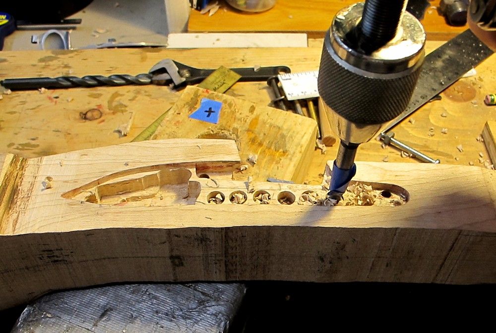
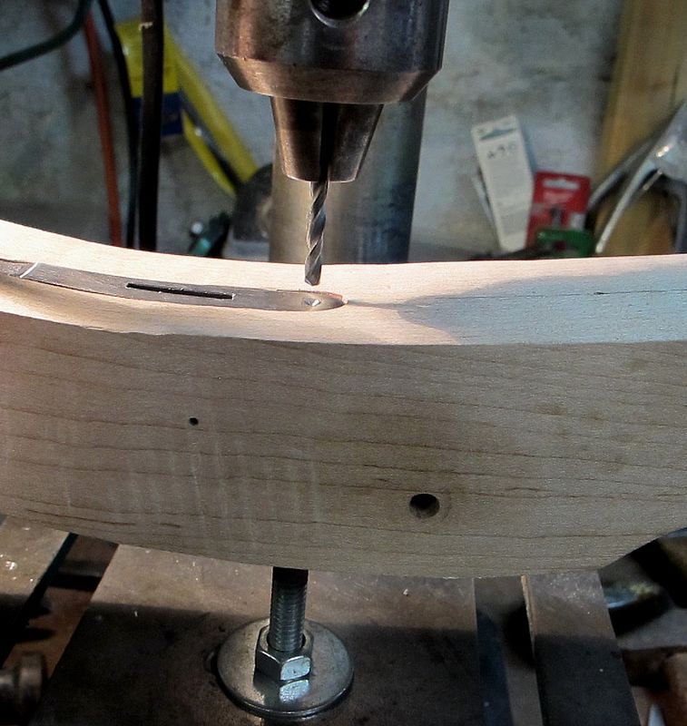
Drilled the 4 barrel lugs last night.
This was about a 75 minute process, 70 minutes of which was set-up, lay-out, re-checking lay-out, and taking barrel in and out and in and out and in and out. (and i only made myself bleed twice
 )
)
If you’re in a hurry, don’t do what I do.
I used two methods to locate each drill spot, and when they agreed with each other, I figured I was good to go.
First method was from Mike Brooks iconic tutorial:
(1) installed barrel, seated it fully rearward and downward and clamped;
(2) scribed line on barrel at top edge of stock above each lug;
(3) removed barrel and measured distance from scribed line on barrel to center of each lug;
(4) transfer that distance to wood for each lug, from top edge down, and make the mark.
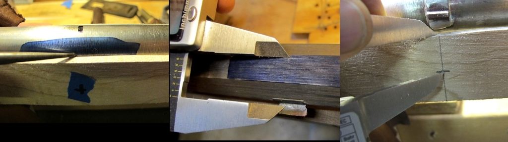
Second (confirmatory) method was passed on to me by BioProf. Thanks BioProf !
I find this one really foolproof if one takes their time and lays it out carefully.
I have a little homemade right angle fence I clamp loosely (at first) to the drillpress table.
Clamped the TOP edge of the barrel to the vertical face of fence (level the barrel with shims too).
Position the whole clamped-together fence-and-barrel-assembly on the drillpress table so that the drill bit hits the lug where it’s supposed to, and then clamp the fence hard to the drillpress table.
Make witness mark on barrel and fence face (at pencil) so I can remove barrel and put it back in same exact spot.
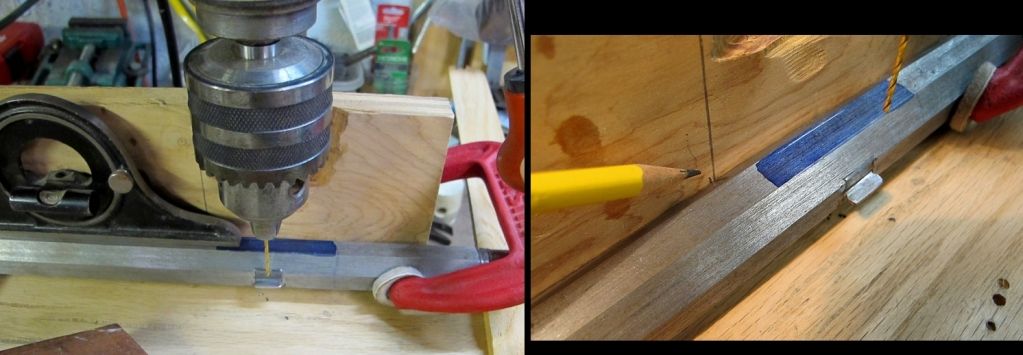
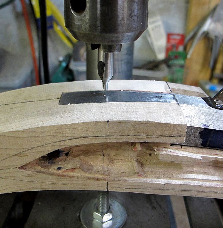
Remove barrel and install it in stock ”“ push down and back and clamped it in, and put the whole thing back on the fence jig.
Matched up the witness marks, and the bit is once again right over the lug (which is now under the wood).
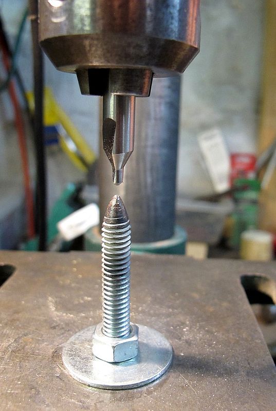
If my drill bit was right over (or very near) the mark from method #1 (which you can see here it was), I drilled the hole.
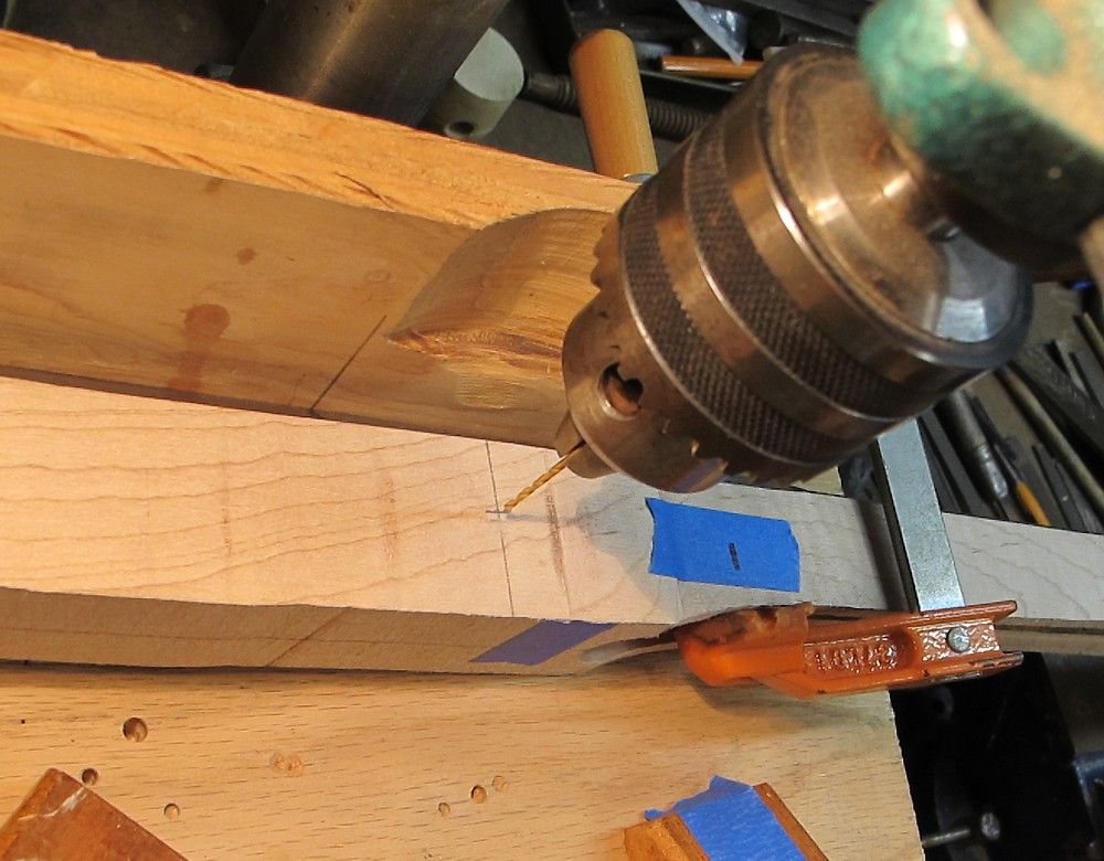
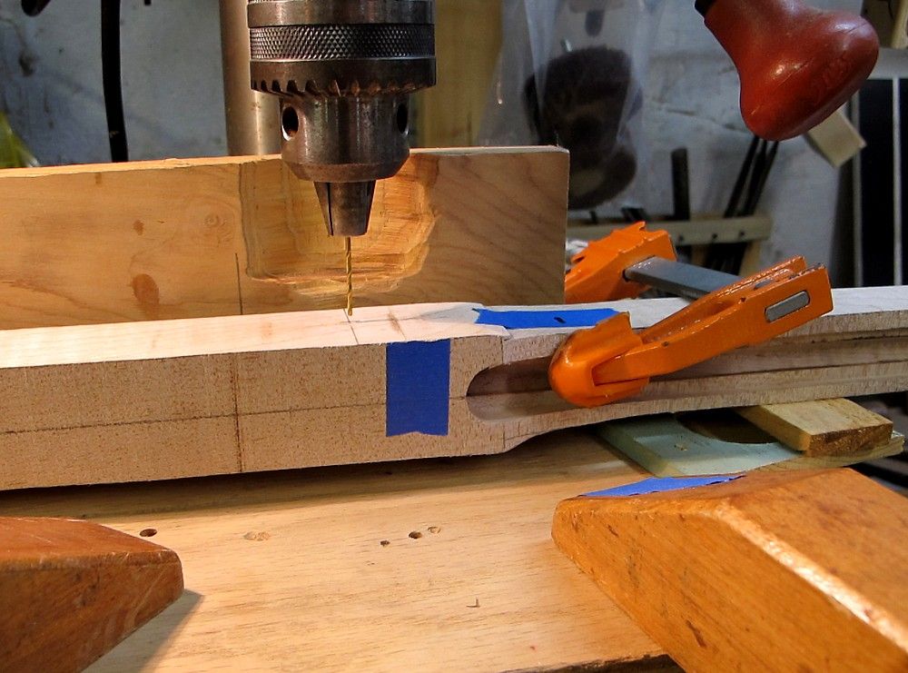
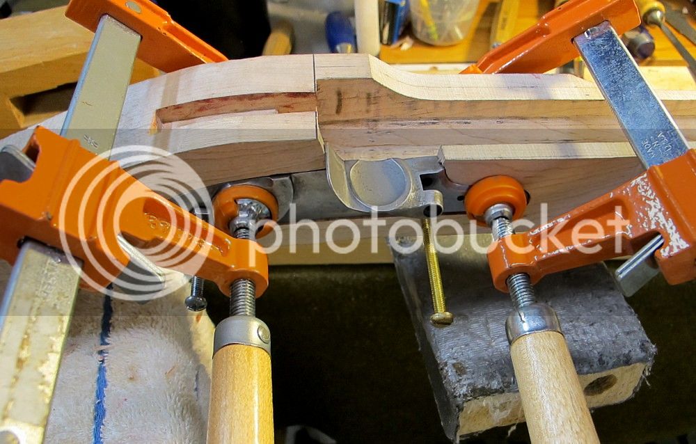
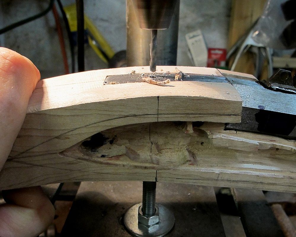
The whole rig looked kinda like this
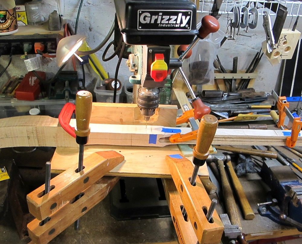
I know I know a lotta messin’ around and clamping and unclamping, but I was 4-for4 hittin’ lugs in the middle, and that’s what I was after.
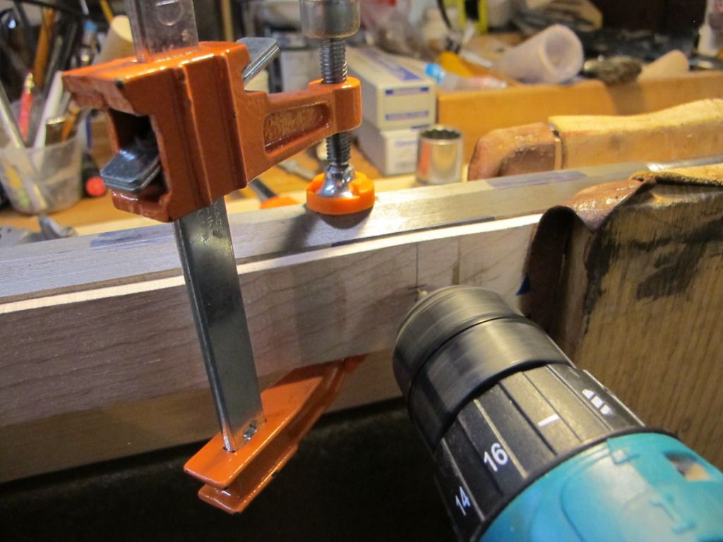
I keep the 1/16” drill bit short in the drill press to minimize wandering.
I use new bits for this everytime - they're cheap.
As such, it only goes thru one side of wood and the lug.
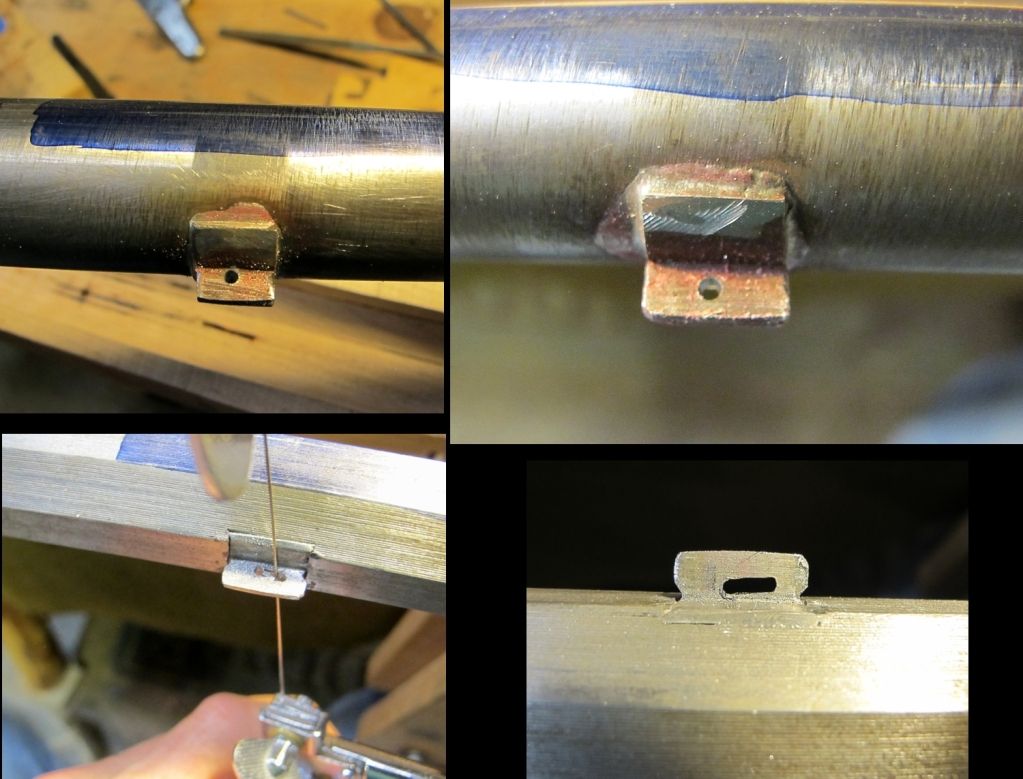
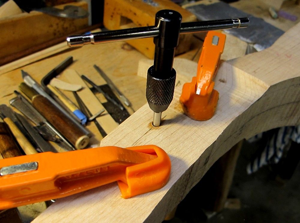
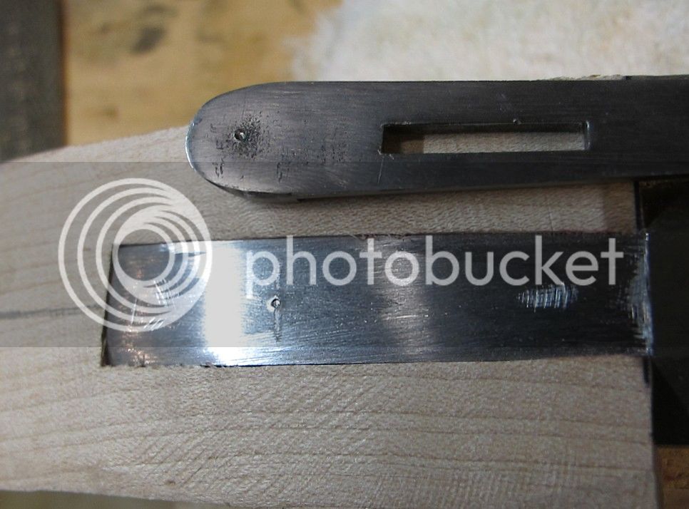
I finish the through-hole off the drill press.
then slotted the holes with jewelers saw and cleaned up with a needle file.
Inlet lock next.
This was about a 75 minute process, 70 minutes of which was set-up, lay-out, re-checking lay-out, and taking barrel in and out and in and out and in and out. (and i only made myself bleed twice
If you’re in a hurry, don’t do what I do.
I used two methods to locate each drill spot, and when they agreed with each other, I figured I was good to go.
First method was from Mike Brooks iconic tutorial:
(1) installed barrel, seated it fully rearward and downward and clamped;
(2) scribed line on barrel at top edge of stock above each lug;
(3) removed barrel and measured distance from scribed line on barrel to center of each lug;
(4) transfer that distance to wood for each lug, from top edge down, and make the mark.
Second (confirmatory) method was passed on to me by BioProf. Thanks BioProf !
I find this one really foolproof if one takes their time and lays it out carefully.
I have a little homemade right angle fence I clamp loosely (at first) to the drillpress table.
Clamped the TOP edge of the barrel to the vertical face of fence (level the barrel with shims too).
Position the whole clamped-together fence-and-barrel-assembly on the drillpress table so that the drill bit hits the lug where it’s supposed to, and then clamp the fence hard to the drillpress table.
Make witness mark on barrel and fence face (at pencil) so I can remove barrel and put it back in same exact spot.
Remove barrel and install it in stock ”“ push down and back and clamped it in, and put the whole thing back on the fence jig.
Matched up the witness marks, and the bit is once again right over the lug (which is now under the wood).
If my drill bit was right over (or very near) the mark from method #1 (which you can see here it was), I drilled the hole.
The whole rig looked kinda like this
I know I know a lotta messin’ around and clamping and unclamping, but I was 4-for4 hittin’ lugs in the middle, and that’s what I was after.
I keep the 1/16” drill bit short in the drill press to minimize wandering.
I use new bits for this everytime - they're cheap.
As such, it only goes thru one side of wood and the lug.
I finish the through-hole off the drill press.
then slotted the holes with jewelers saw and cleaned up with a needle file.
Inlet lock next.
Joe Sullivan
40 Cal.
- Joined
- Jul 27, 2011
- Messages
- 189
- Reaction score
- 0
Sure is coming out nice. :thumbsup:
- Joined
- Jun 12, 2005
- Messages
- 7,970
- Reaction score
- 964
looks great from where i sit!
mikemeteor
45 Cal.
- Joined
- Nov 16, 2008
- Messages
- 660
- Reaction score
- 3
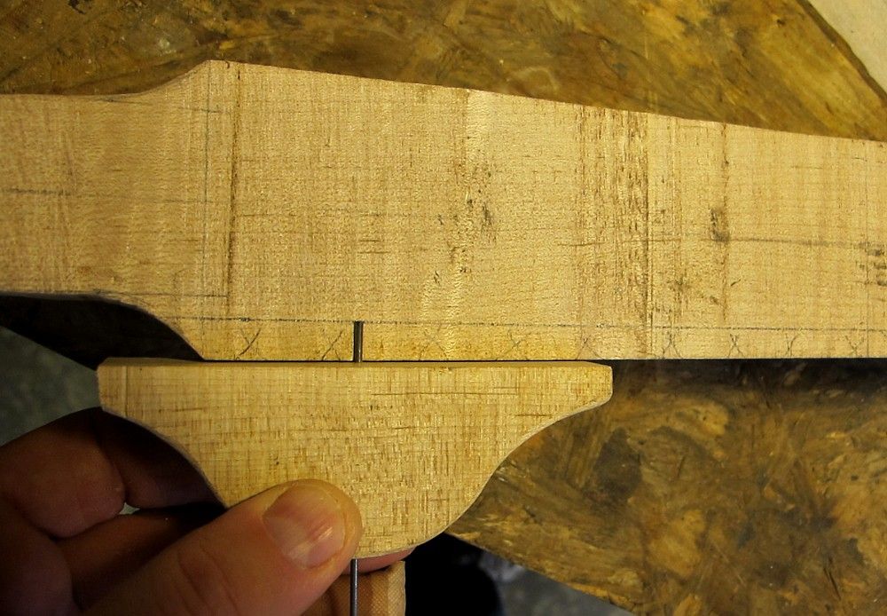
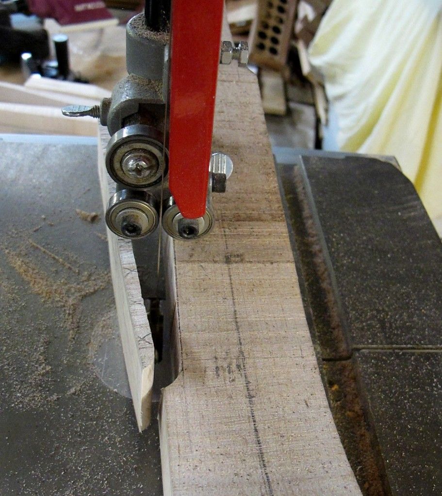
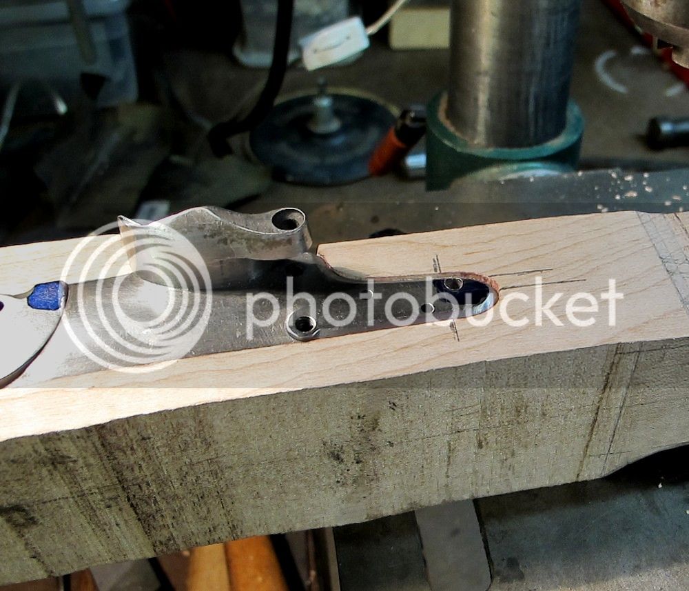
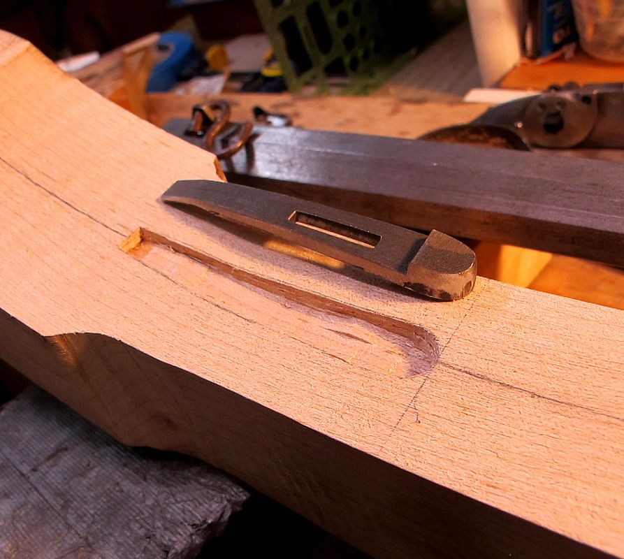
Lockplate and lockbolt holes.
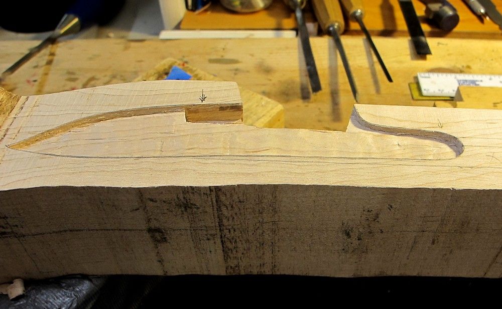
Figured out how thick lock panel needed to be, then added 1/16” or so for safety buffer, laid it on bottom of stock and cut to that line on bandsaw. Using homemade depth gauge ”“ scrap wood and 1/16” music wire friction fit in drilled hole - total cost maybe 10 cents.
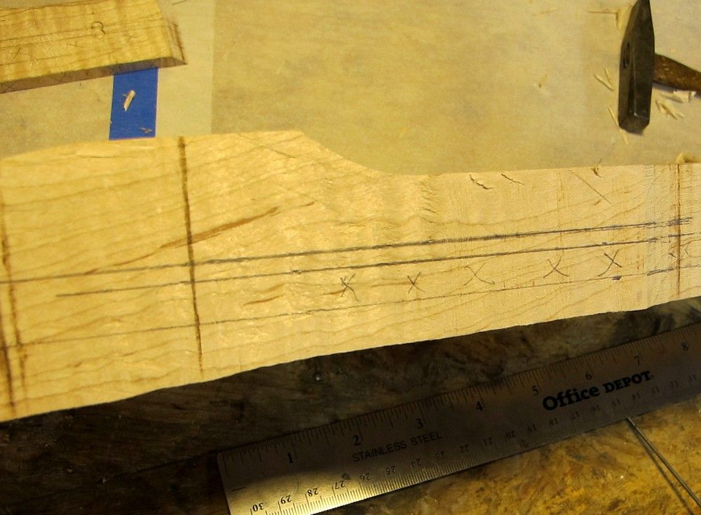
In preparation for lock placement, laid out the RR hole and barrel channel bottom on side of stock. Then clamped lock and tweaked around until I got it looking like I wanted: angle was good, bolt holes were in the right spot, and pan was in correct position to planned touchhole.
Traced around the top of the pan, fence, and bolster, then lipsticked the bolster and replaced it carefully to mark where to chop out for bolster. Then inlet bolster until lockplate laying on lock panel
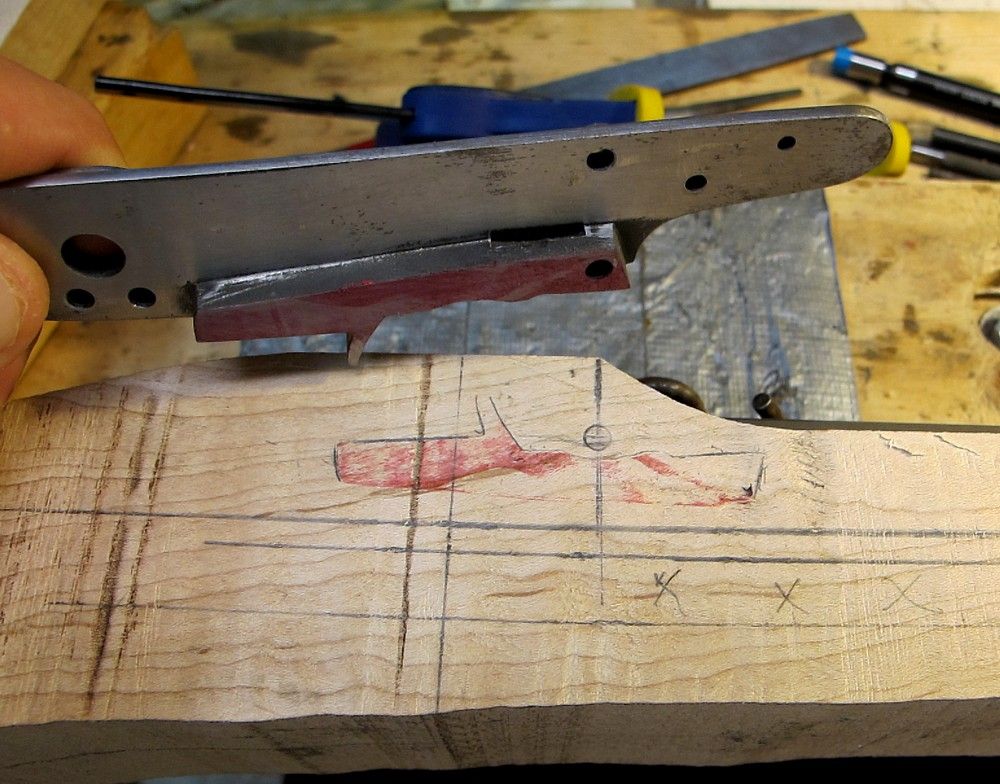
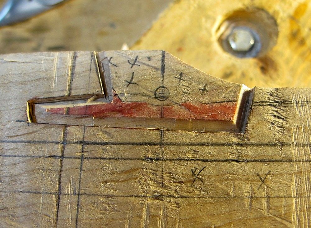
Last chance to adjust lock attitude ! - time to take a break here and think it all through.
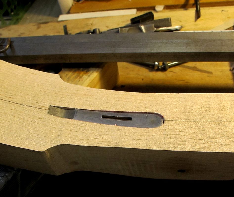
Felt I was good to go so traced around lock panel and inlet it.
I try to keep my inlet really tight (don't we all :shocked2: ). Hard to get the lock plate back out once I tap it in and look for the lipstick marks, so I put bolts in the lock plate - I just screw em in and they hit wood and push the plate straight out. Keeps me from wiggling and torqueing on the lockplate which I think makes the inlet a little more sloppy.
Now I just keep inletting the plate until the bolster hits the barrel.
If I ever get where the surface of the lock plate starts to go below the wood surface of the lock panel , I declare I’m going thru too much wood, and I take the lock panel down another 1/32” or so.
I really try to avoid having to inlet through more wood than absolutely have to.
Next laid out the lock bolt holes.
Time to take a break and think it all through again!
And even at that, I made a small error. You’ll see it.
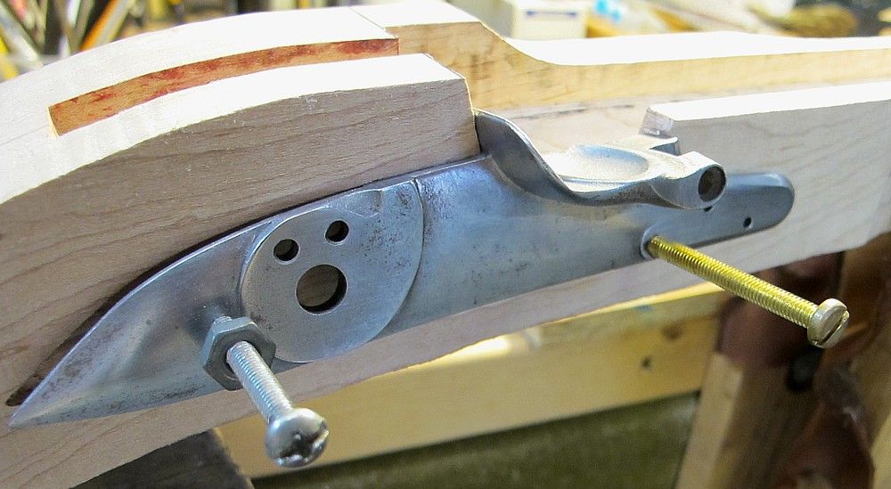
Had to keep in mind that with my sideplate with bolt head bosses already on it, the distance between bolts was already set for me.
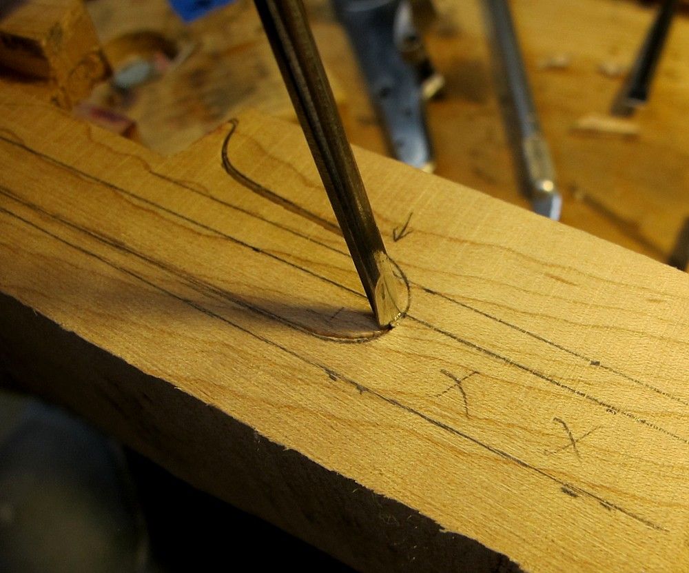
Made sure front bolt would miss RR channel. Drilled that first.
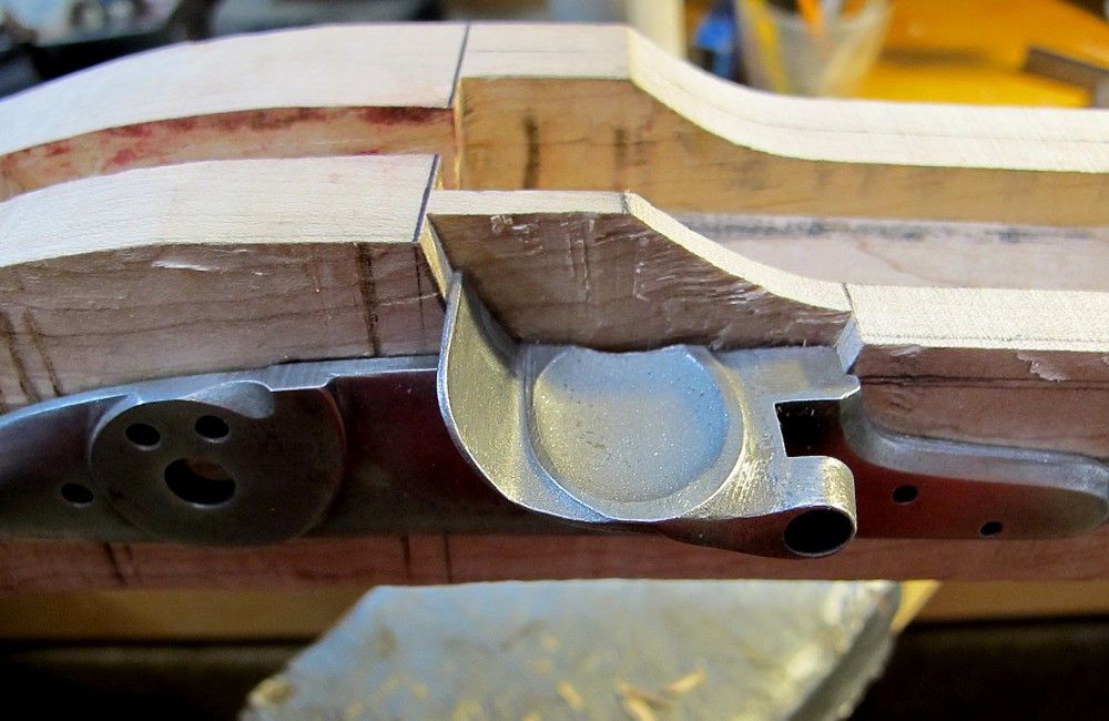
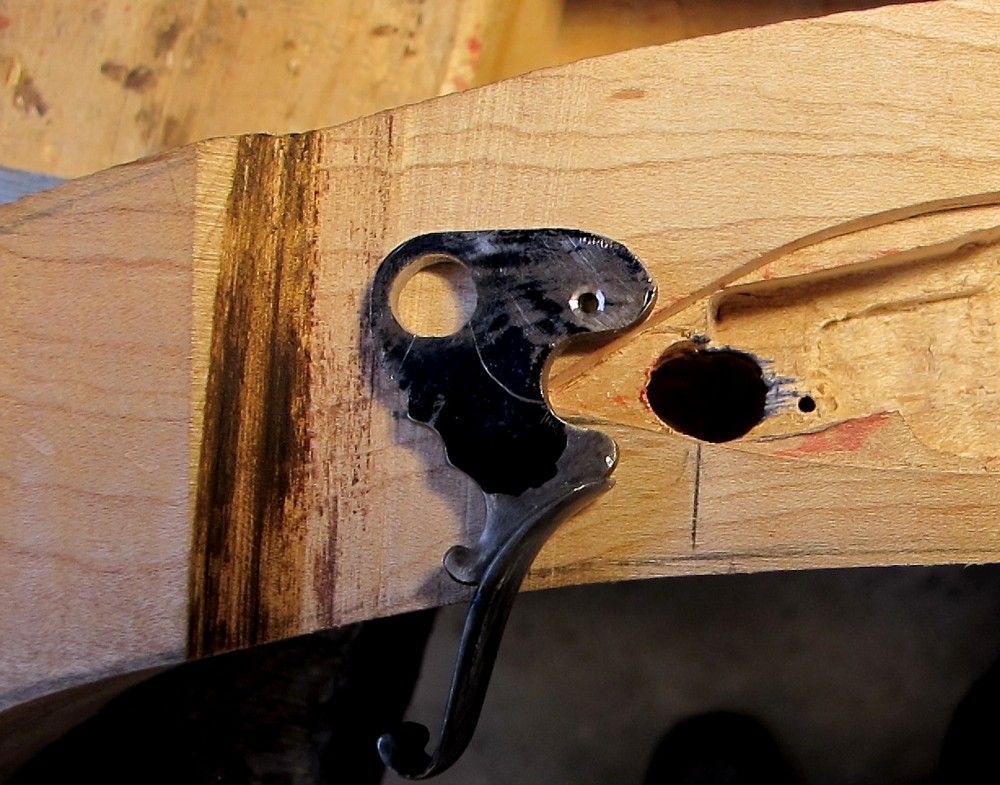
Then used sideplate to declare where the rear bolt needed to be on the lock bolster:
Set that up and drilled it (halfway) from lock side first:
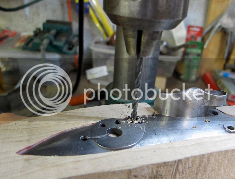
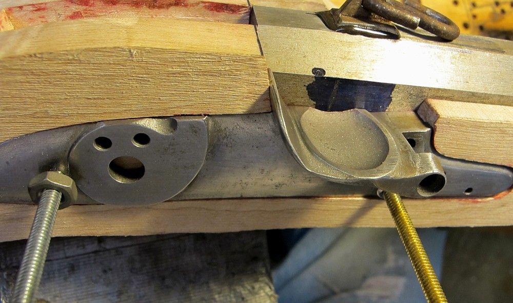
Then drilled it (halfway) from sideplate side, and I got lucky and the two holes met in the middle just right.
Then finished the holes with tap size through the lockplate, and clearance drills thru the wood.
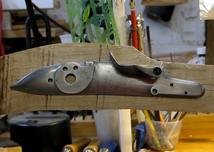
Tapped the lockplate from the sideplate side, and it all came together, except for my one small miscalculation, which I’ll leave to you guys to point out. It ain’t perfect, but I can live with it.
Lock internals next.
(If this is too many pictures, just say so, Zonie ”“ I might be clogging up bandwidth, or boring people to death, or both”¦.).
Figured out how thick lock panel needed to be, then added 1/16” or so for safety buffer, laid it on bottom of stock and cut to that line on bandsaw. Using homemade depth gauge ”“ scrap wood and 1/16” music wire friction fit in drilled hole - total cost maybe 10 cents.
In preparation for lock placement, laid out the RR hole and barrel channel bottom on side of stock. Then clamped lock and tweaked around until I got it looking like I wanted: angle was good, bolt holes were in the right spot, and pan was in correct position to planned touchhole.
Traced around the top of the pan, fence, and bolster, then lipsticked the bolster and replaced it carefully to mark where to chop out for bolster. Then inlet bolster until lockplate laying on lock panel
Last chance to adjust lock attitude ! - time to take a break here and think it all through.
Felt I was good to go so traced around lock panel and inlet it.
I try to keep my inlet really tight (don't we all :shocked2: ). Hard to get the lock plate back out once I tap it in and look for the lipstick marks, so I put bolts in the lock plate - I just screw em in and they hit wood and push the plate straight out. Keeps me from wiggling and torqueing on the lockplate which I think makes the inlet a little more sloppy.
Now I just keep inletting the plate until the bolster hits the barrel.
If I ever get where the surface of the lock plate starts to go below the wood surface of the lock panel , I declare I’m going thru too much wood, and I take the lock panel down another 1/32” or so.
I really try to avoid having to inlet through more wood than absolutely have to.
Next laid out the lock bolt holes.
Time to take a break and think it all through again!
And even at that, I made a small error. You’ll see it.
Had to keep in mind that with my sideplate with bolt head bosses already on it, the distance between bolts was already set for me.
Made sure front bolt would miss RR channel. Drilled that first.
Then used sideplate to declare where the rear bolt needed to be on the lock bolster:
Set that up and drilled it (halfway) from lock side first:
Then drilled it (halfway) from sideplate side, and I got lucky and the two holes met in the middle just right.
Then finished the holes with tap size through the lockplate, and clearance drills thru the wood.
Tapped the lockplate from the sideplate side, and it all came together, except for my one small miscalculation, which I’ll leave to you guys to point out. It ain’t perfect, but I can live with it.
Lock internals next.
(If this is too many pictures, just say so, Zonie ”“ I might be clogging up bandwidth, or boring people to death, or both”¦.).
Bruce Bogart
40 Cal.
- Joined
- Oct 30, 2006
- Messages
- 390
- Reaction score
- 0
Mitch if I'm reading his lockplate correctly he is in the bolster (looks to be a long bolster) and just a touch behind but barely into the breechplug lug. The only thing I don't get is letting a sideplate dictate the bolt pattern. Worked for this build but they seldom work for me. Is it just me :shocked2: ?
Guest
I don't see it, but I'm just a dumb Hungarian who is new to all the building stuff. Something doesn't look right though in the picture where the hand drill is drilling the rear bolt hole. Is it on an angle?
hoochiepapa
75 Cal.
- Joined
- Oct 25, 2010
- Messages
- 5,853
- Reaction score
- 7

I don't think it's boring. I can see where Mike Brines might be because of his level of experience, but for a guy who's only at the "thinking about" a build stage, it's fine. Thanks and I appreciate your detail. Russ
:wink:
:wink:
Guest
Russ... I think Mike was using the sleeping icon because he is waiting for an answer from the OP.
mikemeteor
45 Cal.
- Joined
- Nov 16, 2008
- Messages
- 660
- Reaction score
- 3
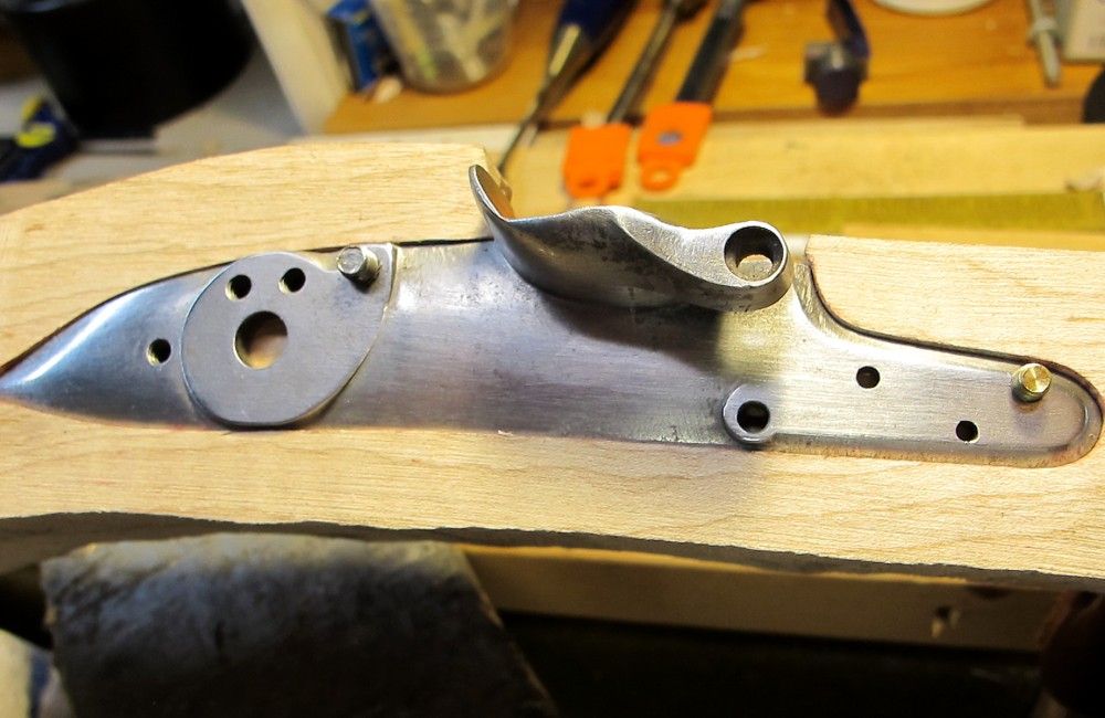
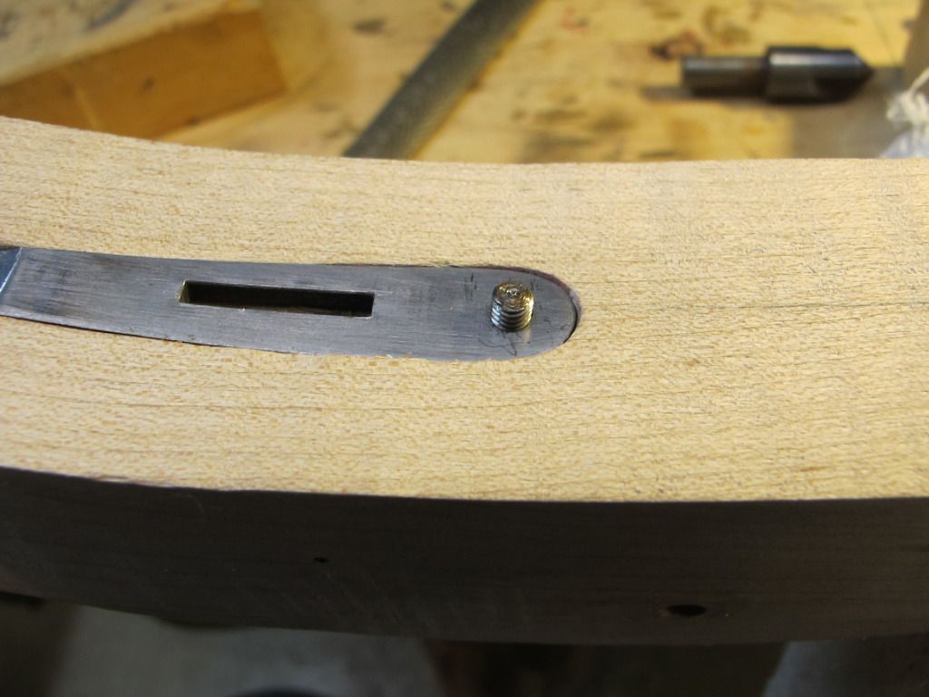
My earlier mistake - the front lock-bolt hole infringed on the bevel of the face of the lockplate - kinda hard to see from the angle of the photo.
About 1/4 of the bolt is on the bevel - that's probably classified "less than optimal".
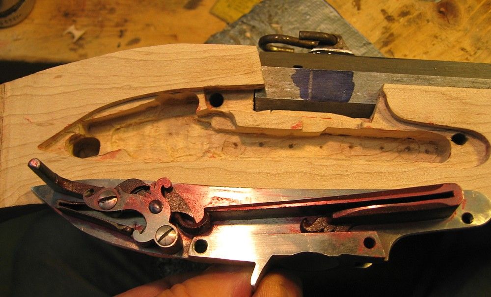
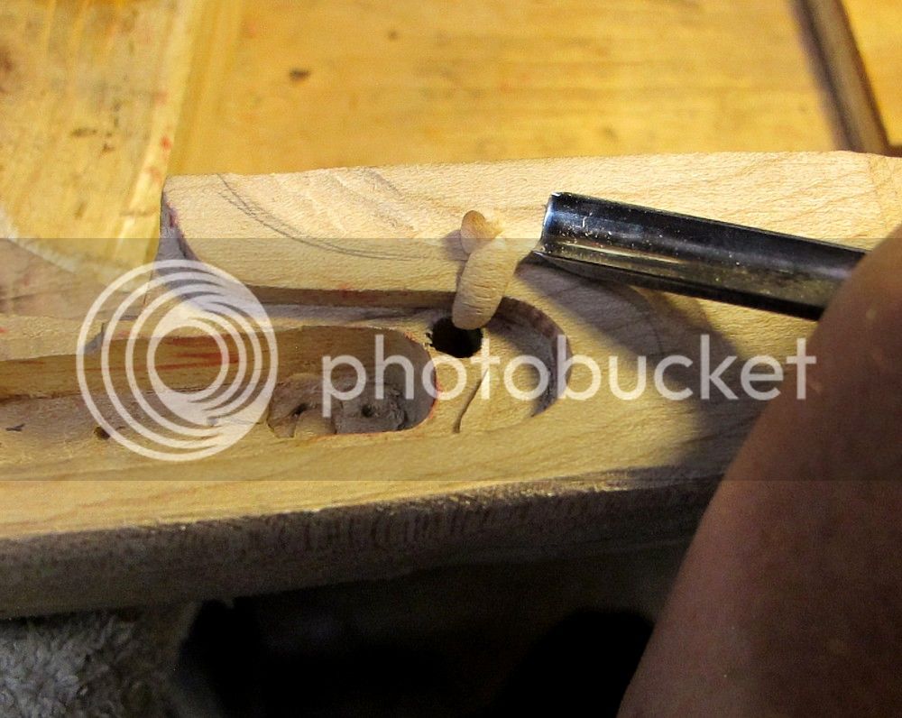
Lock internals
Pretty mundane stuff.
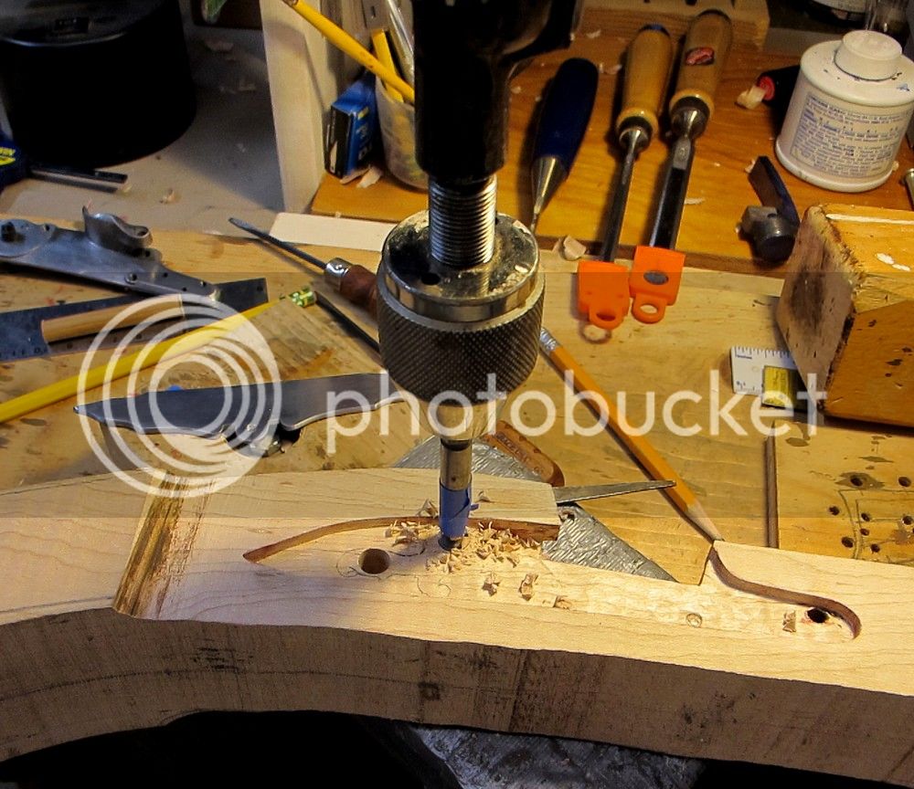
Trace the bridle, measure the depth, and hand egg beater drill with small forstner bit.
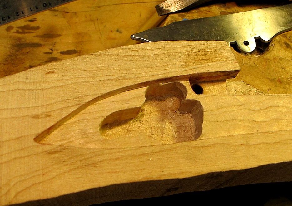
chisel out the webs.
Lipstick, fit the lock, and slice off the red.
I did just barely break into the barrel channel for a small distance at the front of the mainspring cavity.
Of course, inlet has to be clear in both "at rest" and "full cock" position.
I insert lock at rest, and then slowly crank it back to full cock with small crescent on the tumbler post - feeling for interference.
After that, it's a pain to go from full cock back to "at rest" for the next "cut and fit" trial - I put the mainspring vice on (and off) every time to let it off easy. Tedious.
Is this the way folks do it?
I assuming you should not release the sear and let the spring snap to the full extent of the tumbler (with no hammer stop) ... Any tips here ?
/mike
About 1/4 of the bolt is on the bevel - that's probably classified "less than optimal".
Lock internals
Pretty mundane stuff.
Trace the bridle, measure the depth, and hand egg beater drill with small forstner bit.
chisel out the webs.
Lipstick, fit the lock, and slice off the red.
I did just barely break into the barrel channel for a small distance at the front of the mainspring cavity.
Of course, inlet has to be clear in both "at rest" and "full cock" position.
I insert lock at rest, and then slowly crank it back to full cock with small crescent on the tumbler post - feeling for interference.
After that, it's a pain to go from full cock back to "at rest" for the next "cut and fit" trial - I put the mainspring vice on (and off) every time to let it off easy. Tedious.
Is this the way folks do it?
I assuming you should not release the sear and let the spring snap to the full extent of the tumbler (with no hammer stop) ... Any tips here ?
/mike
mikemeteor
45 Cal.
- Joined
- Nov 16, 2008
- Messages
- 660
- Reaction score
- 3
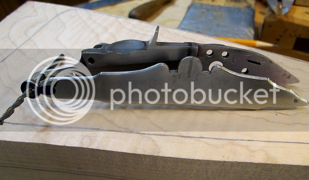
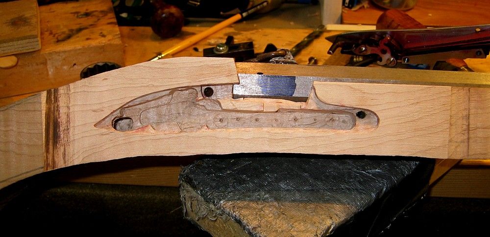
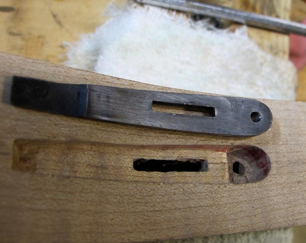
Time to install the trigger.
I'm using a simple pinned trigger.
Most of the work is layout and ciphering, which doesn't photograph too well.
I don't think I'll have too much of an issue with here with the tricky part where front foot of TG bow meets front of trigger plate.
The front sprue was cut off, and the front lug, just ahead of the trigger plate, was narrowed (from the rear). See more of that later during TG inlet.
I'm using a "captured" sear bar, where the sear extension goes through a hole in the trigger blade.
My sear extension inlet was a tad larger than I needed, and this forced me to put the pin just under 1/2" from the bar.
I can maybe adjust this later if it feels to sloppy.
The other end of the trigger pin of course exits at a spot which will be under the sideplate.
I didn't get a picture of it, but I did the trigger inlet with a series of holes drilled to depth and then cleaned up with a small chisel.
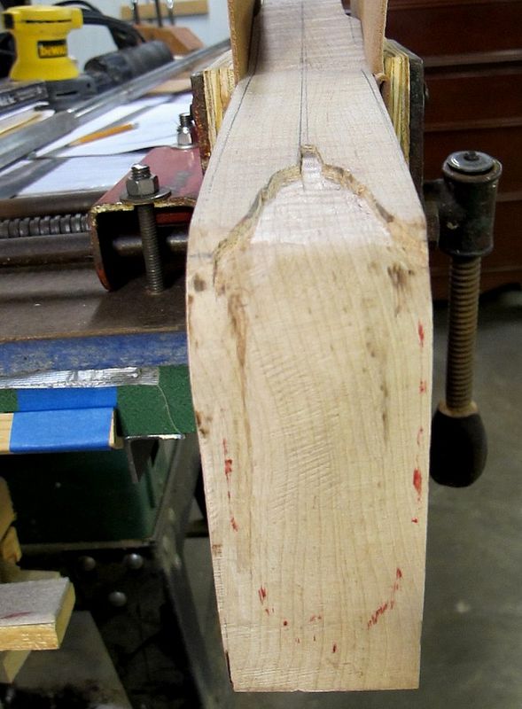
With the trigger in place, I measured just under 14" LOP and set started the buttplate inlet.
Cut off the excess buttstock close to the line.
Just barley had enough wood for my 1/8" cast off.
Actually had to cheat back on it a little.
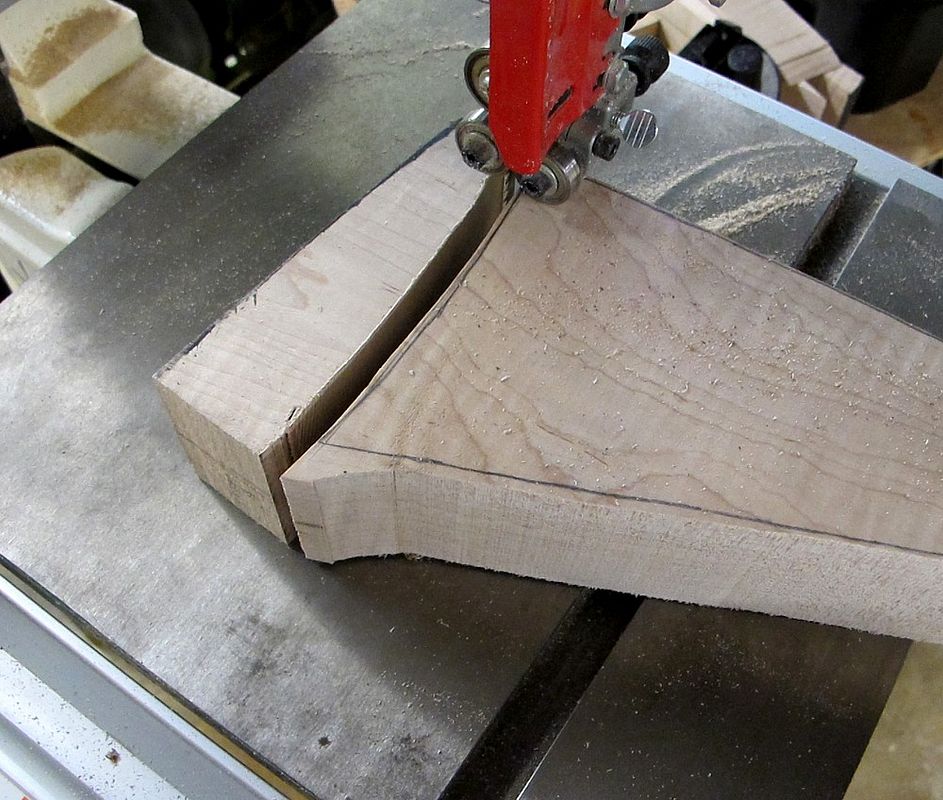
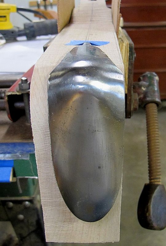
OK. A mistake here. I cut the buttstock to the pattern line as opposed to the buttplate line.
The buttplate has a small bend out at the toe.
I could inlet the whole thing that much further, but this is my first fowler wrap-around buttplate job, and I didn't want to make it harder than it's already going to be.
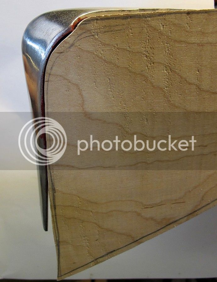
So I decided to bring in the toe of the plate to better match the wood profile.
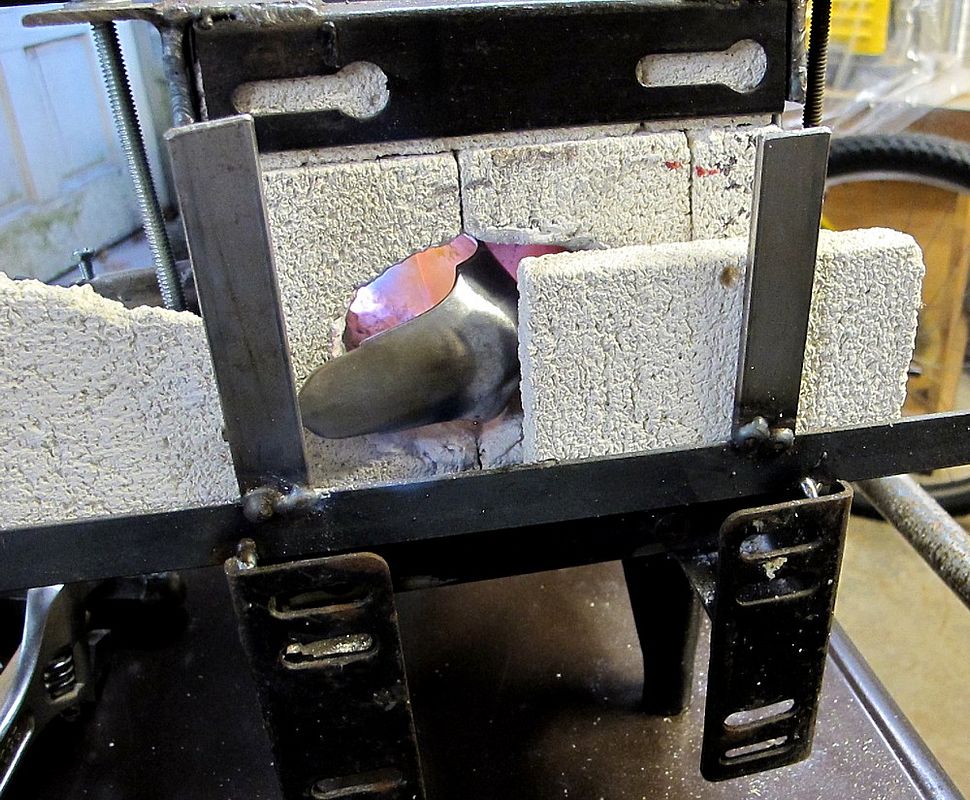
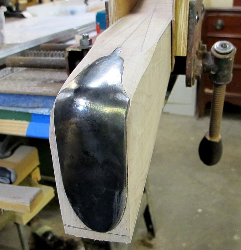
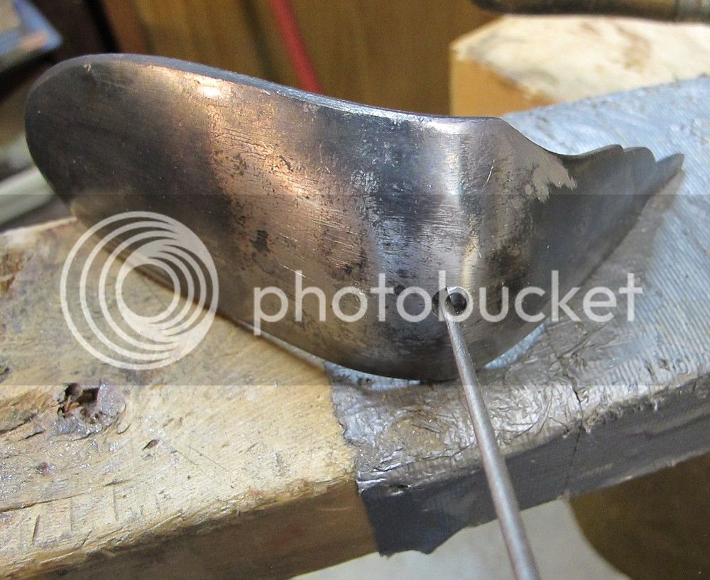
Stuck the buttplate in my propane mini-forge and got it red-yellow hot in about 3 minutes.
Banged it out straigter on my small anvil. this took two hands and no time for photos.
Results below.
It's kinda straight, but I can live with it.
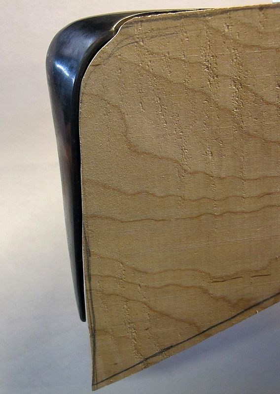
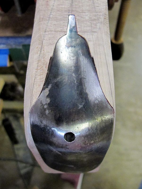
Started the buttplate inlet.
"DOWN AND IN !" I was instructed for these fowler buttplates.
I'm still workin on it, but geez I admit I'm a little worried about what to do around that corner bend part, where "down" turns into "in" in a not-so-clear way.
I'm still working it in - I'm assuming the gaps close up as I go in further.
[The way I understand it, with a brass buttplate, its common to bang the metal around to conform to where to you need to close gaps. That aint gonna happen so much with this steel. So I'm left to fine tune the wood inlet itself. I'm all ears to any tips !)
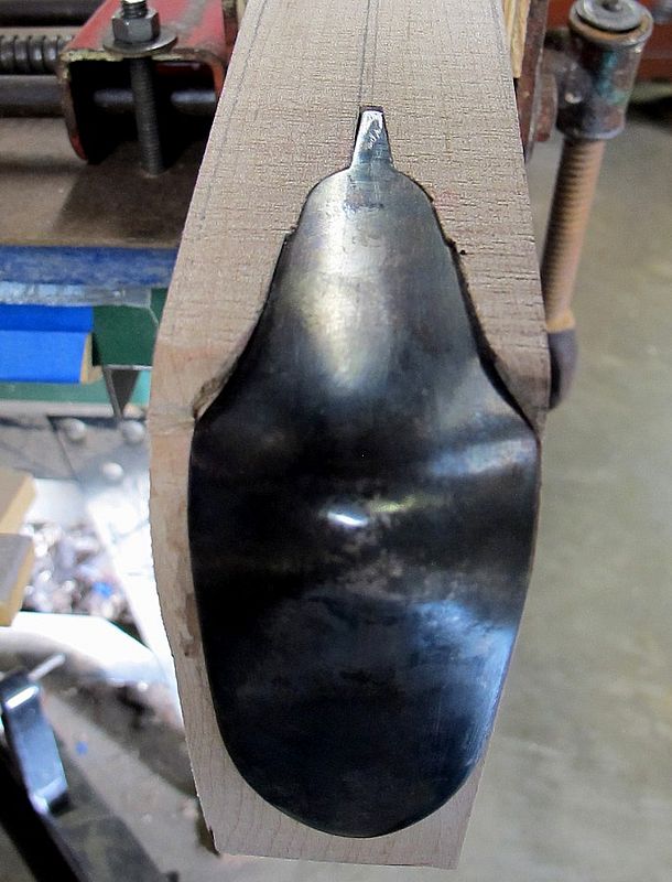
I still have about 1/8" straight forward to go.
Merry Christmas everyone!
/mike
I'm using a simple pinned trigger.
Most of the work is layout and ciphering, which doesn't photograph too well.
I don't think I'll have too much of an issue with here with the tricky part where front foot of TG bow meets front of trigger plate.
The front sprue was cut off, and the front lug, just ahead of the trigger plate, was narrowed (from the rear). See more of that later during TG inlet.
I'm using a "captured" sear bar, where the sear extension goes through a hole in the trigger blade.
My sear extension inlet was a tad larger than I needed, and this forced me to put the pin just under 1/2" from the bar.
I can maybe adjust this later if it feels to sloppy.
The other end of the trigger pin of course exits at a spot which will be under the sideplate.
I didn't get a picture of it, but I did the trigger inlet with a series of holes drilled to depth and then cleaned up with a small chisel.
With the trigger in place, I measured just under 14" LOP and set started the buttplate inlet.
Cut off the excess buttstock close to the line.
Just barley had enough wood for my 1/8" cast off.
Actually had to cheat back on it a little.
OK. A mistake here. I cut the buttstock to the pattern line as opposed to the buttplate line.
The buttplate has a small bend out at the toe.
I could inlet the whole thing that much further, but this is my first fowler wrap-around buttplate job, and I didn't want to make it harder than it's already going to be.
So I decided to bring in the toe of the plate to better match the wood profile.
Stuck the buttplate in my propane mini-forge and got it red-yellow hot in about 3 minutes.
Banged it out straigter on my small anvil. this took two hands and no time for photos.
Results below.
It's kinda straight, but I can live with it.
Started the buttplate inlet.
"DOWN AND IN !" I was instructed for these fowler buttplates.
I'm still workin on it, but geez I admit I'm a little worried about what to do around that corner bend part, where "down" turns into "in" in a not-so-clear way.
I'm still working it in - I'm assuming the gaps close up as I go in further.
[The way I understand it, with a brass buttplate, its common to bang the metal around to conform to where to you need to close gaps. That aint gonna happen so much with this steel. So I'm left to fine tune the wood inlet itself. I'm all ears to any tips !)
I still have about 1/8" straight forward to go.
Merry Christmas everyone!
/mike
mikemeteor
45 Cal.
- Joined
- Nov 16, 2008
- Messages
- 660
- Reaction score
- 3
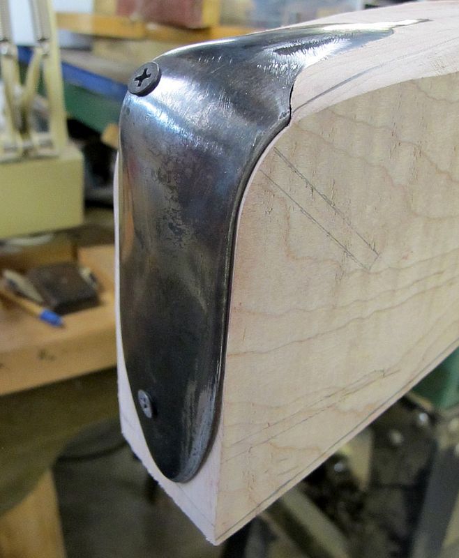
OK. Lordy. 4 sessions and about 10 hrs later, I finally got the buttplate in. That’s about twice as long as it takes me for a deep crescent mountain rifle buttplate.
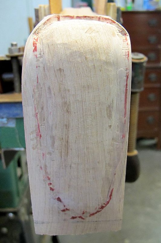
Drilled the screw holes for the buttplate.
The pilot hole on the heel was off-center ”“ I’m good at doing that, even with a punch start. ?
Tried a trick I learned on the forum to walk a hole sideways ”“ and it seemed to work.
Filed a small groove on the side I wanted to move to, and drilled with a bit just a hair larger than existing hole.
The reduced resistance on the grooved side allows the hole to re-center a bit, I suppose is the theory.
Anyway, it seemed to work.
Drilled the toehole and tacked the buttplate on with temporary screws.
Tried hard to have the pilot screwholes in the stock angled such that the screw head will settle nicely in the countersink.
I use simple visual guides to help me orient the drill how I want it.

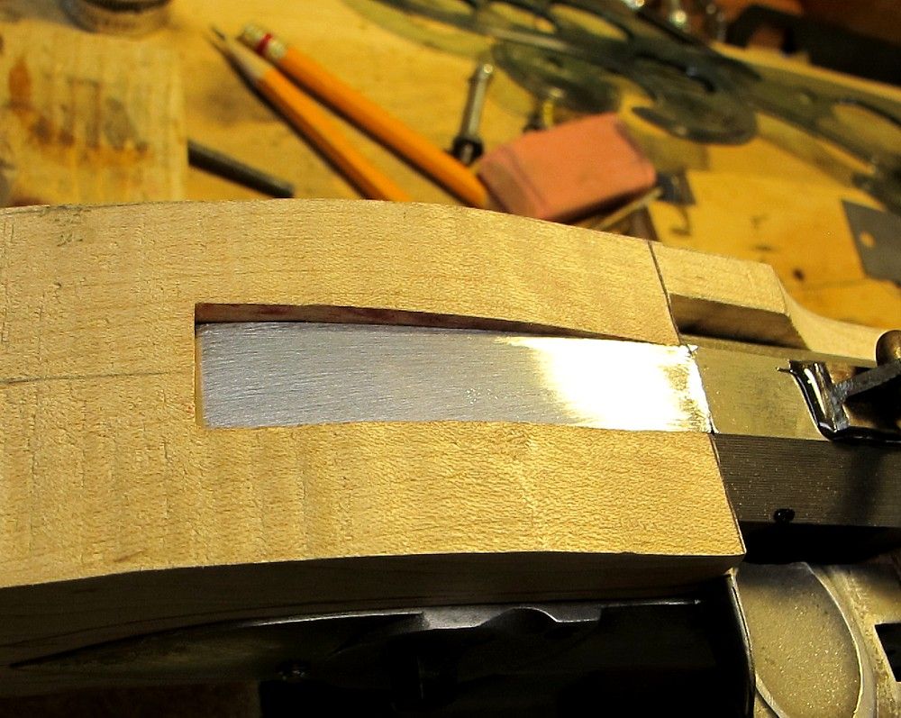
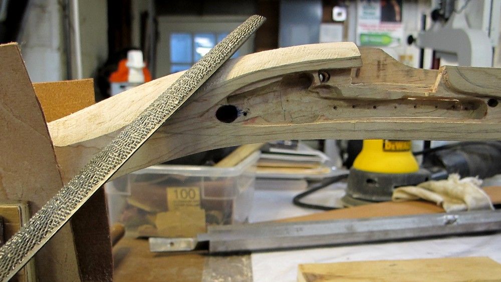
Before installing the tang bolt, I needed to file my tang down to near-final contour, so that :
(1) I could start the down-slope of the wrist right at the barrel breech, and
(2) I would know how to orient the tang bolt to the final surface of the tang.
Used the grinder and a lot of elbow grease with a file, and took about 3/16” or more worth of meat off the top of the tang.
It now curves nicely into the wrist.
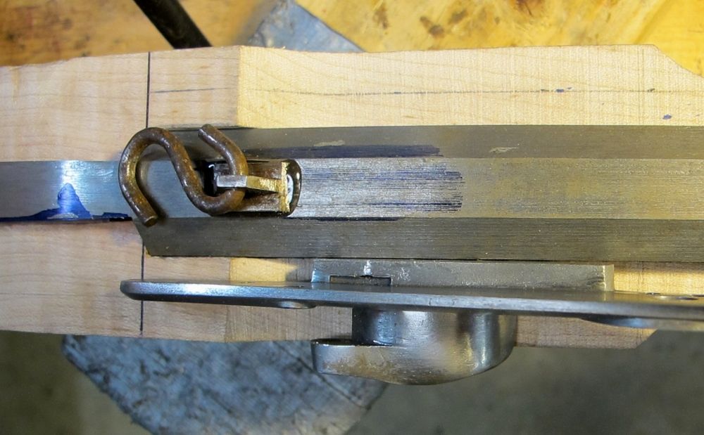
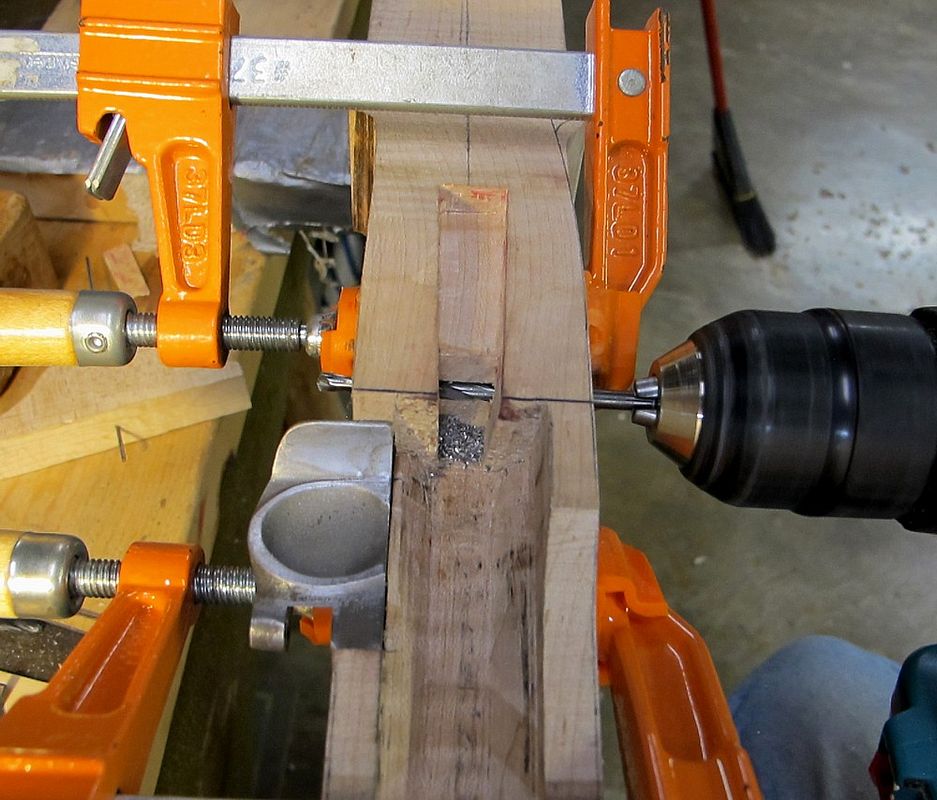
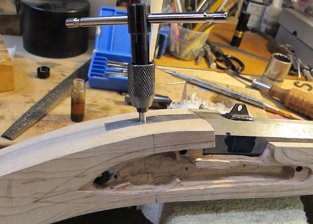
Break out the point-to-point drilling jig for the tang bolt job. I punched where I wanted the centers on the trigger plate and the tang.
I also dimpled the trigger plate punch a little deeper with a countersink, so the jig point would stay home in it.
I start my holes with center drills to further minimize wandering, and then switch to twist bits.
I drilled halfway from the top with a 1/8”, and flipped the stock and drill the bottom half.
The two holes met nicely in the middle.
I then used a tapping-sized bit to drill the trigger plate from the bottom; then removed the trigger plate and drilled the rest with a clearance bit (from the top).
Tapped the plate through the stock.
Going at it from both sides got me the hole in the trigger plate where I wanted it ”“ I have been burned on this before when drilling from the top and the bit walked on me when it hit the underside of the trigger plate boss.
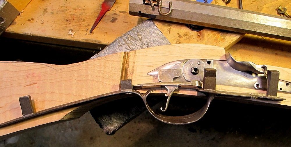
I had sketched in my lock panel earlier, so now it was time to start roughing out the lock and wrist area.
The Stanley #49 and #50 make pretty quick work of it.
When I got close to a line, I switched to my Pferd half-round cabinet file (which I really like) ”“ it leaves a nice surface, ready for scraping.
Since the radius on the front of the lockplate is smaller, I went at that with a 8mm 7 sweep Pfeil gouge, plus some files and sandpaper on a dowel.
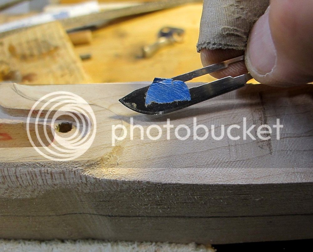
I have found that the traditional scalpel blades also have a very handy shape to them for scraping these smaller radius’s (radii?).
You can tweak the angle up and down and get the radius you’re after.
I also used a utility knife blade scraper to sneak up to the final line of the lock plate margin.
Now why do you guess I needed that Band-aid ?
Scraping with utility blades (or carpet knife blades, etc) is something I picked up from Mark Wheland at Dixon’s last year.
It’s handy, they’re pretty cheap, sharp, and it works great.
He showed how to put a hook on them too, if anyone’s interested.
Enough for now.
Maybe too much. Anyone still awake?
Tomorrow I’ll transfer the lockplate shape to the sideplate side and rough in that side.
/mm
Drilled the screw holes for the buttplate.
The pilot hole on the heel was off-center ”“ I’m good at doing that, even with a punch start. ?
Tried a trick I learned on the forum to walk a hole sideways ”“ and it seemed to work.
Filed a small groove on the side I wanted to move to, and drilled with a bit just a hair larger than existing hole.
The reduced resistance on the grooved side allows the hole to re-center a bit, I suppose is the theory.
Anyway, it seemed to work.
Drilled the toehole and tacked the buttplate on with temporary screws.
Tried hard to have the pilot screwholes in the stock angled such that the screw head will settle nicely in the countersink.
I use simple visual guides to help me orient the drill how I want it.
Before installing the tang bolt, I needed to file my tang down to near-final contour, so that :
(1) I could start the down-slope of the wrist right at the barrel breech, and
(2) I would know how to orient the tang bolt to the final surface of the tang.
Used the grinder and a lot of elbow grease with a file, and took about 3/16” or more worth of meat off the top of the tang.
It now curves nicely into the wrist.
Break out the point-to-point drilling jig for the tang bolt job. I punched where I wanted the centers on the trigger plate and the tang.
I also dimpled the trigger plate punch a little deeper with a countersink, so the jig point would stay home in it.
I start my holes with center drills to further minimize wandering, and then switch to twist bits.
I drilled halfway from the top with a 1/8”, and flipped the stock and drill the bottom half.
The two holes met nicely in the middle.
I then used a tapping-sized bit to drill the trigger plate from the bottom; then removed the trigger plate and drilled the rest with a clearance bit (from the top).
Tapped the plate through the stock.
Going at it from both sides got me the hole in the trigger plate where I wanted it ”“ I have been burned on this before when drilling from the top and the bit walked on me when it hit the underside of the trigger plate boss.
I had sketched in my lock panel earlier, so now it was time to start roughing out the lock and wrist area.
The Stanley #49 and #50 make pretty quick work of it.
When I got close to a line, I switched to my Pferd half-round cabinet file (which I really like) ”“ it leaves a nice surface, ready for scraping.
Since the radius on the front of the lockplate is smaller, I went at that with a 8mm 7 sweep Pfeil gouge, plus some files and sandpaper on a dowel.
I have found that the traditional scalpel blades also have a very handy shape to them for scraping these smaller radius’s (radii?).
You can tweak the angle up and down and get the radius you’re after.
I also used a utility knife blade scraper to sneak up to the final line of the lock plate margin.
Now why do you guess I needed that Band-aid ?
Scraping with utility blades (or carpet knife blades, etc) is something I picked up from Mark Wheland at Dixon’s last year.
It’s handy, they’re pretty cheap, sharp, and it works great.
He showed how to put a hook on them too, if anyone’s interested.
Enough for now.
Maybe too much. Anyone still awake?
Tomorrow I’ll transfer the lockplate shape to the sideplate side and rough in that side.
/mm
mikemeteor
45 Cal.
- Joined
- Nov 16, 2008
- Messages
- 660
- Reaction score
- 3
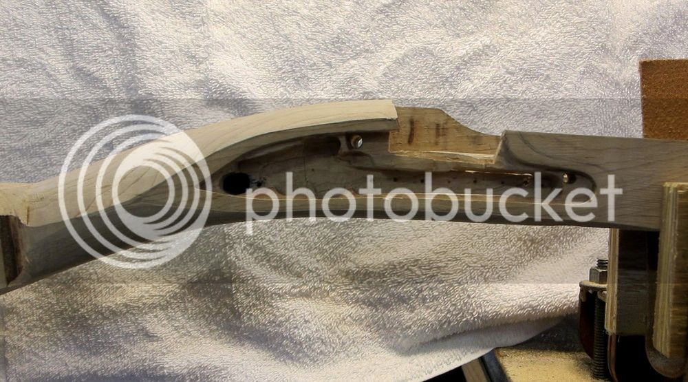
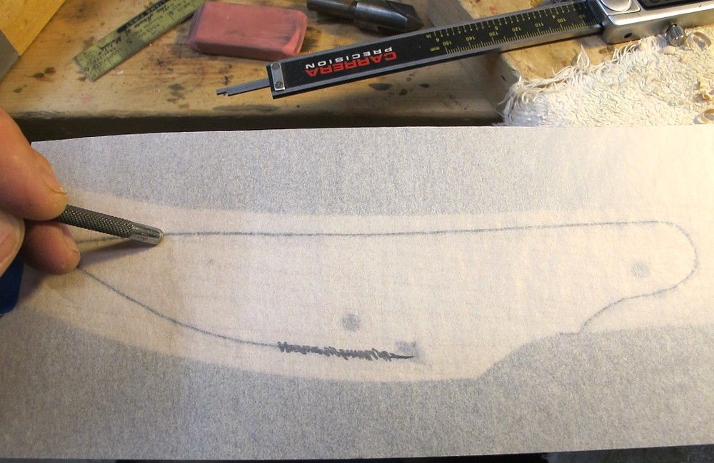
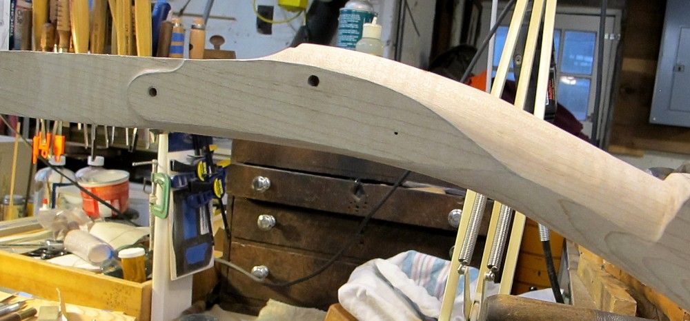
Used the pencil lead transfer method to duplicate shape of lock panel on the sideplate side.
Rubbed off with the blunt end of my pointy scribe tool.
Then rasped and carved in that the sideplate lock panel down to the line.
Gave everything an initial smoothing with scrapers.
These lock panels are still almost 1/16” above final grade yet, so I’ll be back to them later, tweaking everything when the rest of the stock shaping all comes together. If it ever does.
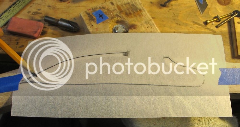
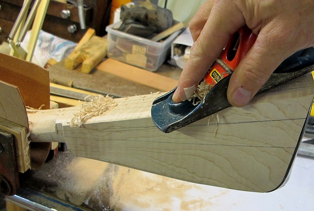
Then on to rough shaping the buttstock.
Used planes as much as possible, followed by the Nicholson rasps and files.
Landmarks at this point were the existing wrist and of course the buttplate margin.
This is hard going without an original or desirable contemporary in hand, from which to take measurements and constantly check lines and proportions.
In essence, I’m going off pictures, which we all know is tenuous, and my own eye for what looks good, which I guarantee you is suspect. There’s a reason I’m not an artist.
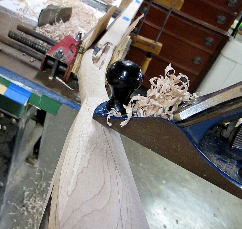
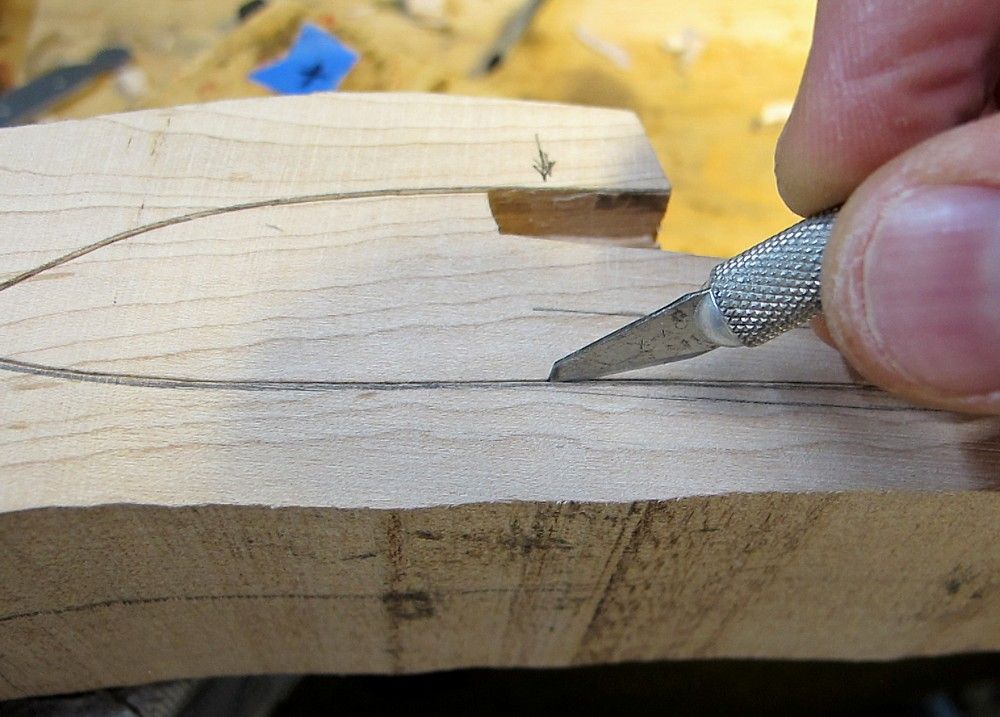
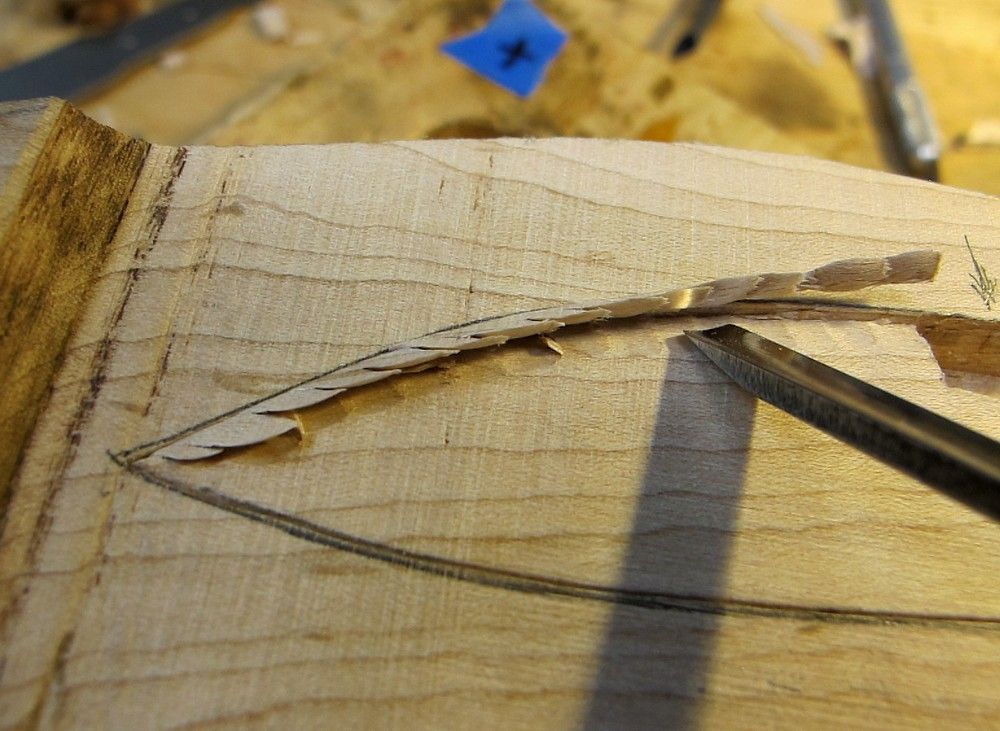
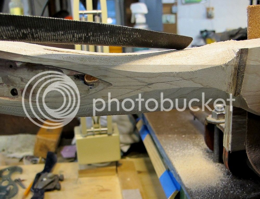
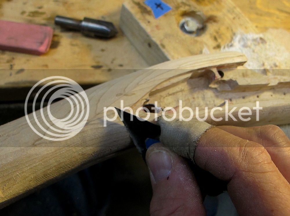
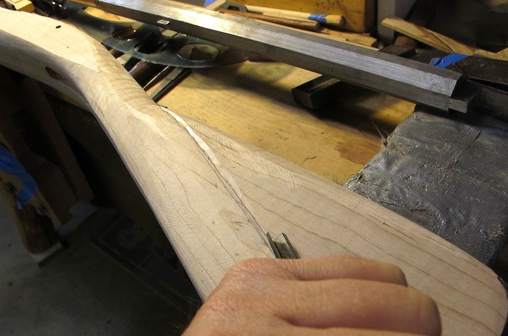
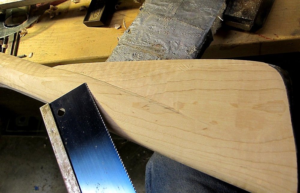
Next step was to start carrying the wrist down into the butt.
After a lot of pencil and eraser work, I cut in the initial line with a V-gouge.
I then took the wobbles out of that, and deepened it a bit, with my dovetail saw and some files.
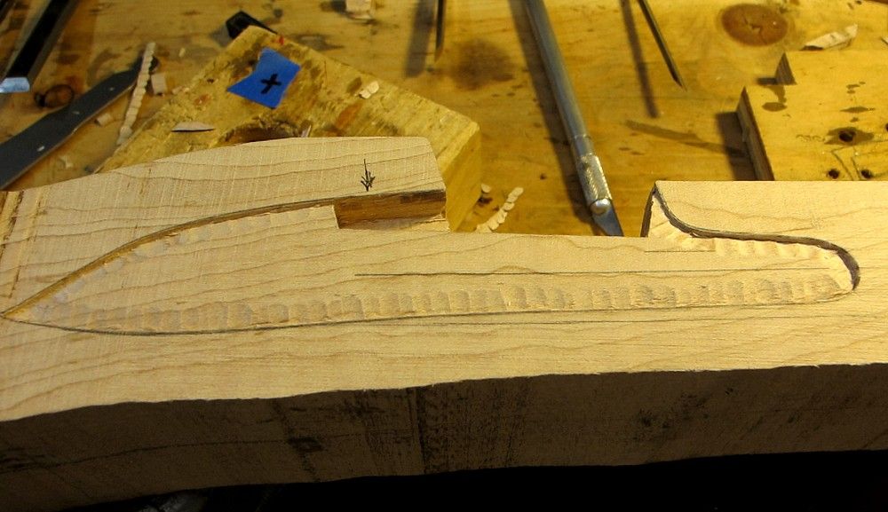
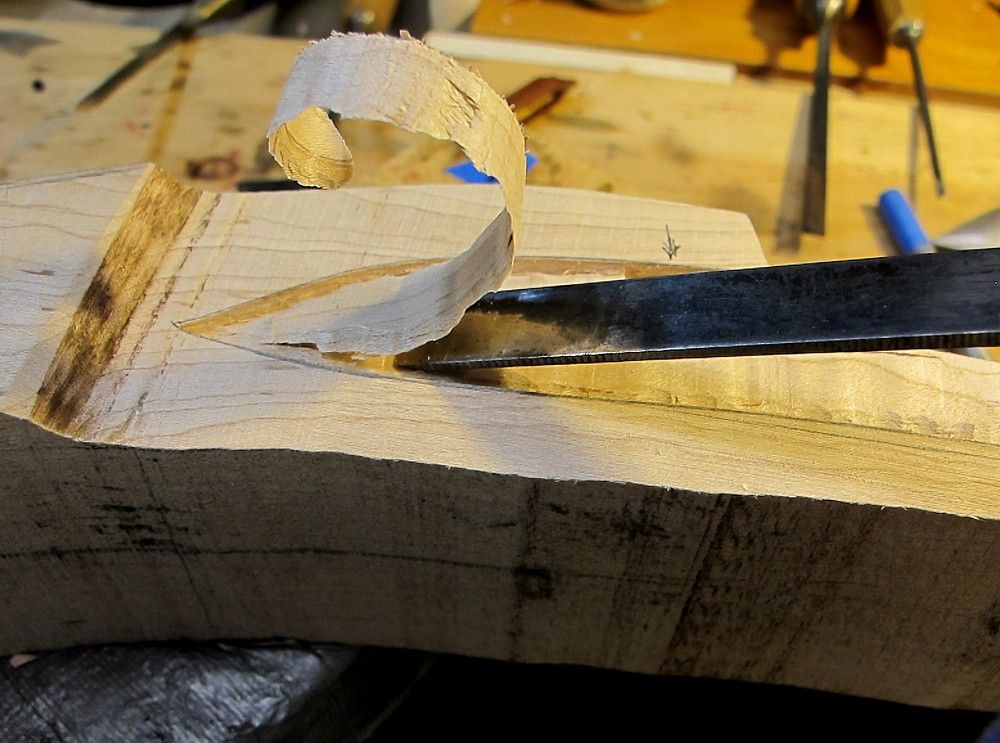
Then I just chiseled away, first at the comb, then at the wrist, then back to the comb, etc etc until I was approaching the desired shape.
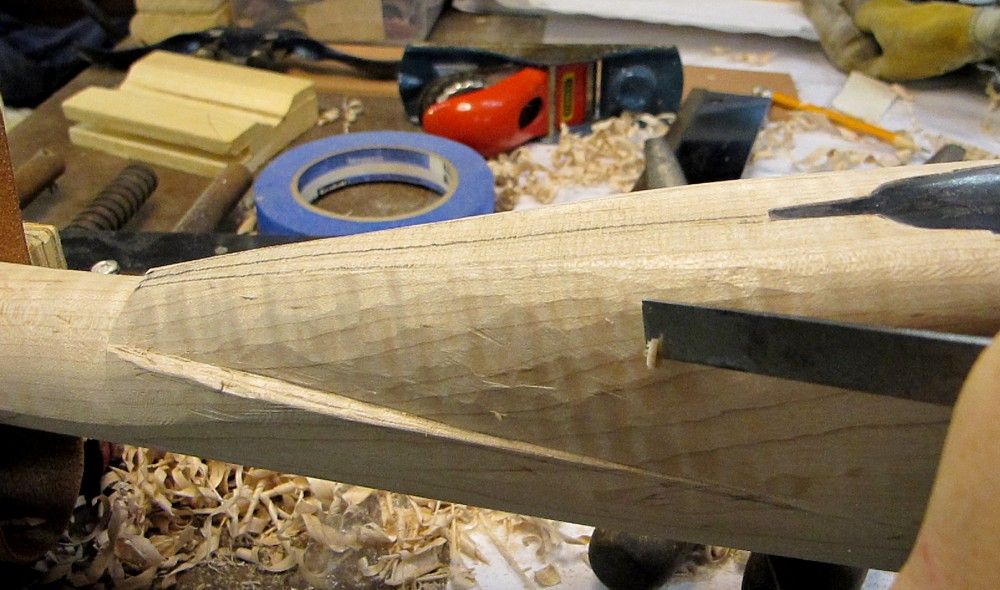
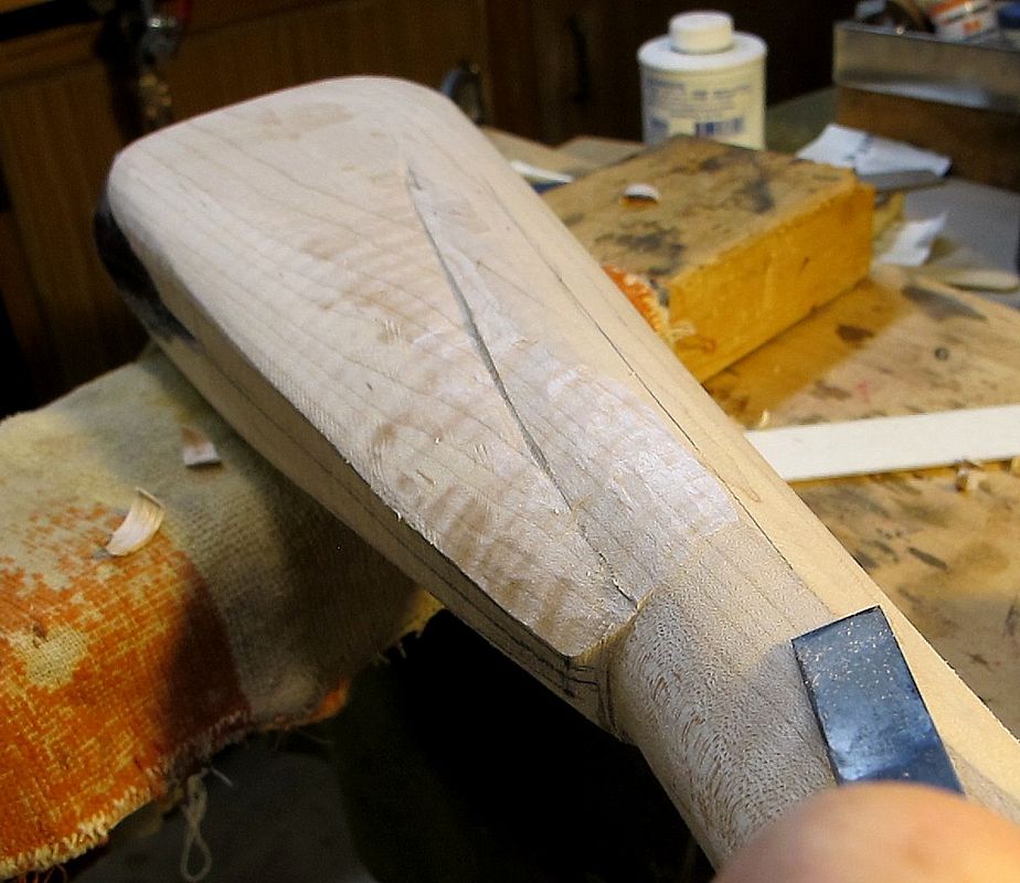
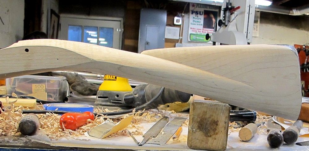
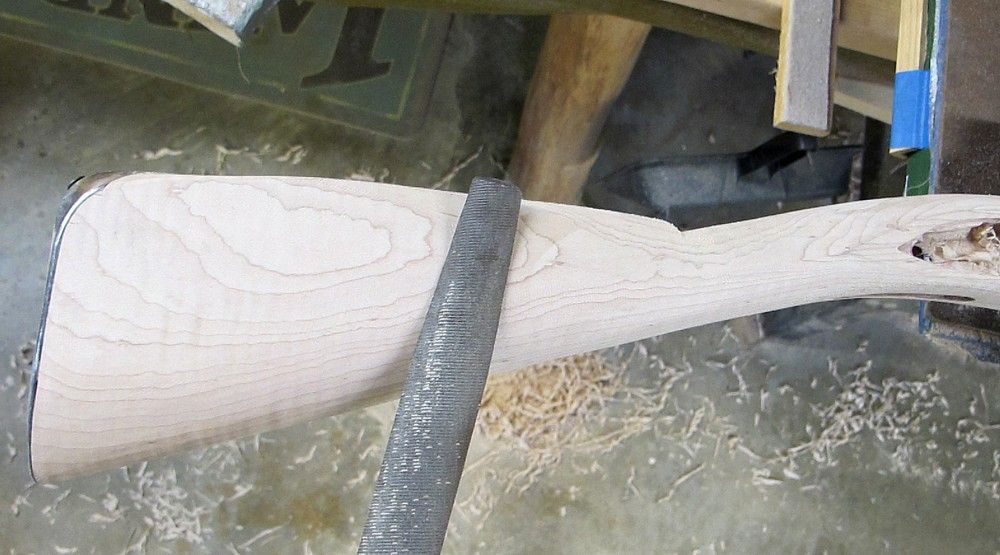
I still have MUCH slimming and trimming to do on every surface, but I’m sneaking up on it pretty slow.
Was just thinking to get the rough overall form in place, and then go back and do the slimming/reduction on everything from the lock panel back, hopefully in some form of harmony or flow.
Don’t hesitate to point out errors and design flaws - a big reason why I’m sharing this build is to get critical feedback before it’s too late.
/mm
Rubbed off with the blunt end of my pointy scribe tool.
Then rasped and carved in that the sideplate lock panel down to the line.
Gave everything an initial smoothing with scrapers.
These lock panels are still almost 1/16” above final grade yet, so I’ll be back to them later, tweaking everything when the rest of the stock shaping all comes together. If it ever does.
Then on to rough shaping the buttstock.
Used planes as much as possible, followed by the Nicholson rasps and files.
Landmarks at this point were the existing wrist and of course the buttplate margin.
This is hard going without an original or desirable contemporary in hand, from which to take measurements and constantly check lines and proportions.
In essence, I’m going off pictures, which we all know is tenuous, and my own eye for what looks good, which I guarantee you is suspect. There’s a reason I’m not an artist.
Next step was to start carrying the wrist down into the butt.
After a lot of pencil and eraser work, I cut in the initial line with a V-gouge.
I then took the wobbles out of that, and deepened it a bit, with my dovetail saw and some files.
Then I just chiseled away, first at the comb, then at the wrist, then back to the comb, etc etc until I was approaching the desired shape.
I still have MUCH slimming and trimming to do on every surface, but I’m sneaking up on it pretty slow.
Was just thinking to get the rough overall form in place, and then go back and do the slimming/reduction on everything from the lock panel back, hopefully in some form of harmony or flow.
Don’t hesitate to point out errors and design flaws - a big reason why I’m sharing this build is to get critical feedback before it’s too late.
/mm
Guest
Looks really nice Mike. Just curious... what type of plane would you recommend for someone who may need to get one? I'm not to the shaping part just yet, but will be eventually and should start to look at what tools I may need to do that. I don't own a plane, but I do have a set of scrapers and the sureform flat file.
Similar threads
- Replies
- 22
- Views
- 831
- Replies
- 10
- Views
- 1K
- Replies
- 112
- Views
- 6K
- Replies
- 10
- Views
- 694
- Locked
- Replies
- 2
- Views
- 559
