• This community needs YOUR help today. We rely 100% on Supporting Memberships to fund our efforts. With the ever increasing fees of everything, we need help. We need more Supporting Members, today. Please invest back into this community. I will ship a few decals too in addition to all the account perks you get.


    Sign up here: https://www.muzzleloadingforum.com/account/upgrades
  • Friends, our 2nd Amendment rights are always under attack and the NRA has been a constant for decades in helping fight that fight.

    We have partnered with the NRA to offer you a discount on membership and Muzzleloading Forum gets a small percentage too of each membership, so you are supporting both the NRA and us.

    Use this link to sign up please; https://membership.nra.org/recruiters/join/XR045103

Rebuilding a Mendi Wheellock

Muzzleloading Forum

Help Support Muzzleloading Forum:

This site may earn a commission from merchant affiliate links, including eBay, Amazon, and others.
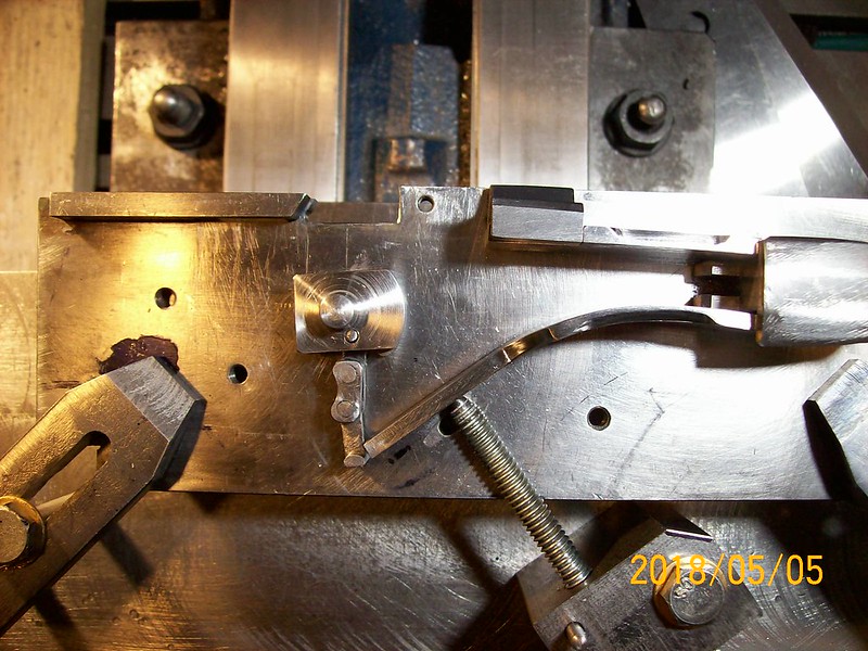
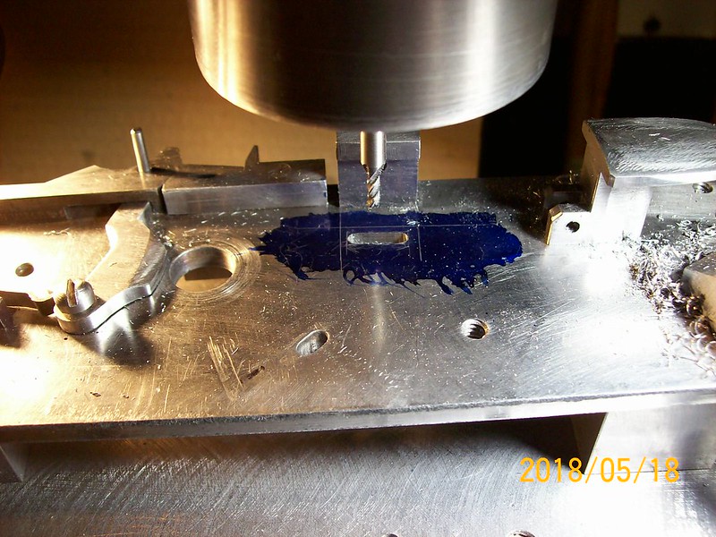
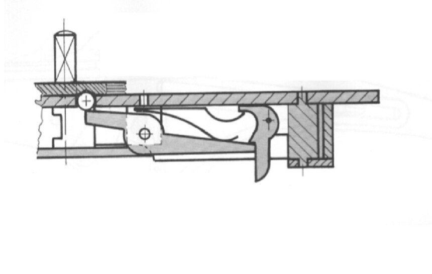
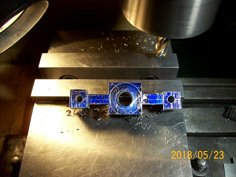
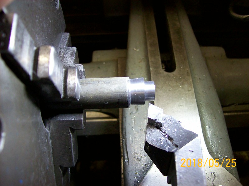
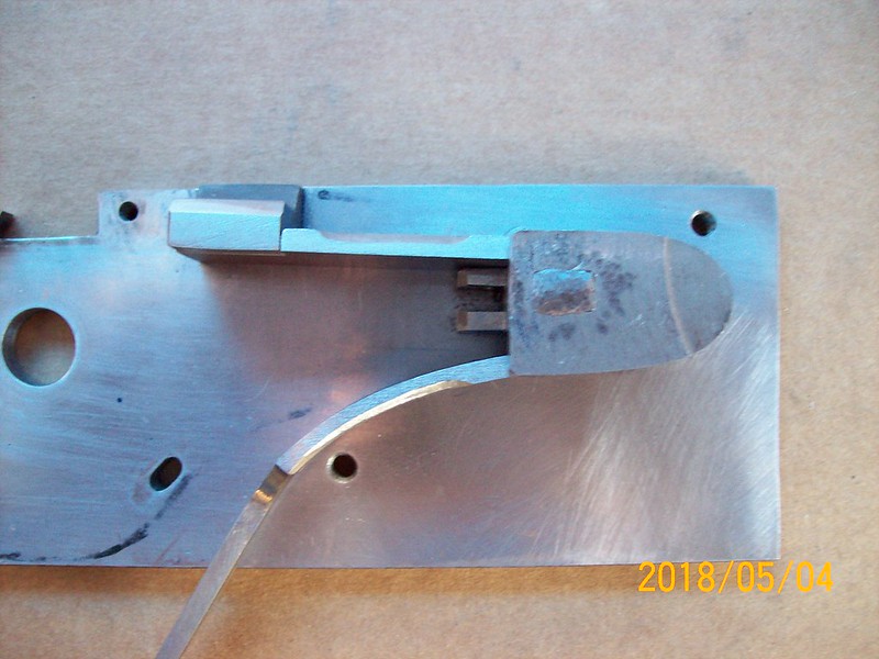
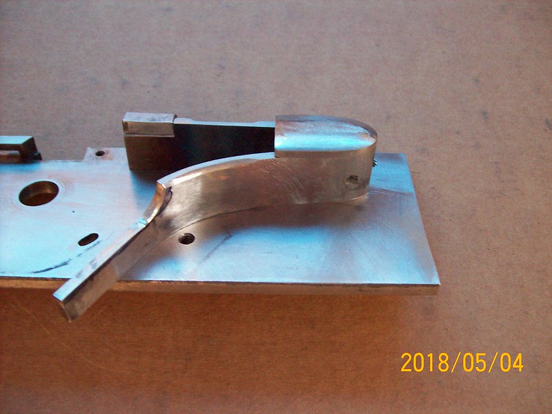
Progress photos - mainspring support riveted thru lockplate and top of the support riveted on after (side view). The sear will pivot inside this part.
100_0592

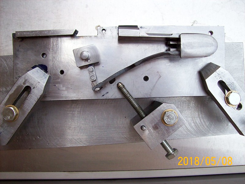
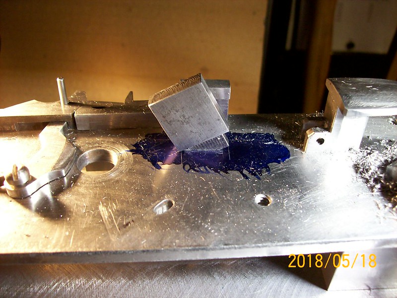
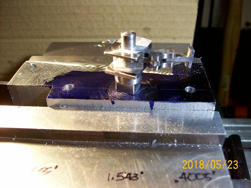
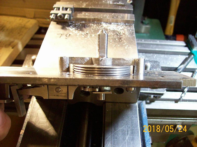
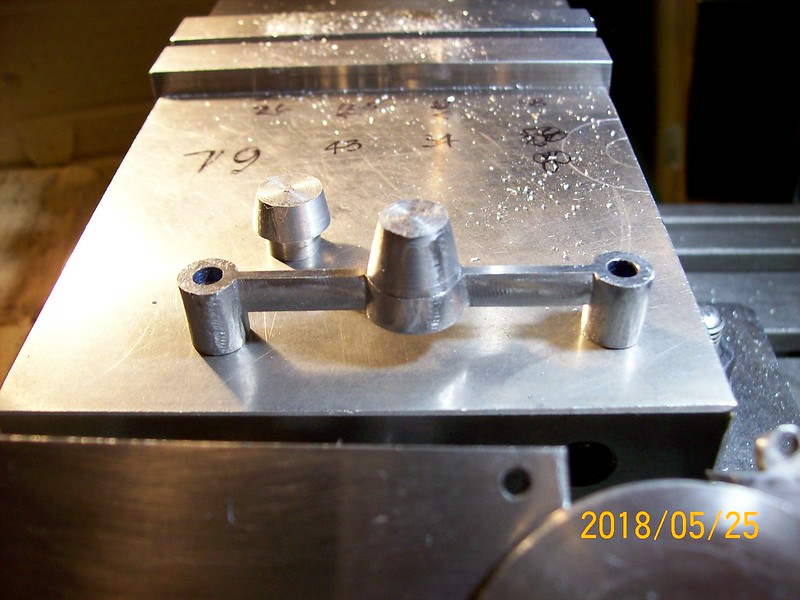
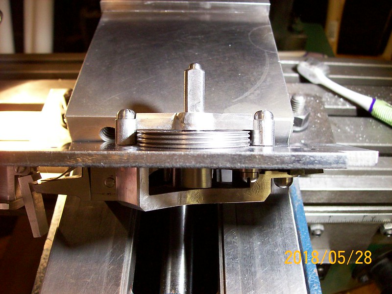
View showing mainspring support top rivet - used the 16 oz. machinist hammer this time. You can see that the mainspring bears against the support. I made the part asymmetric.
100_0594

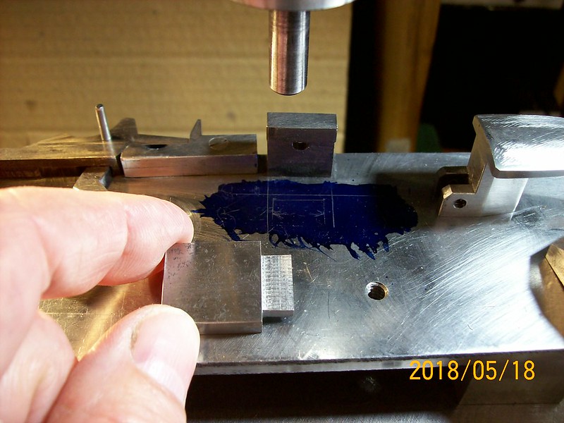
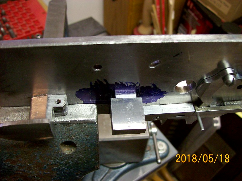
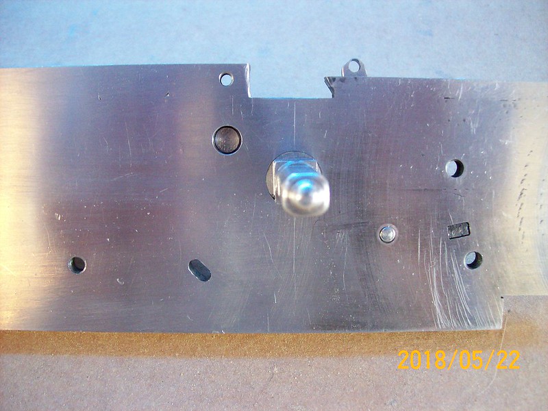
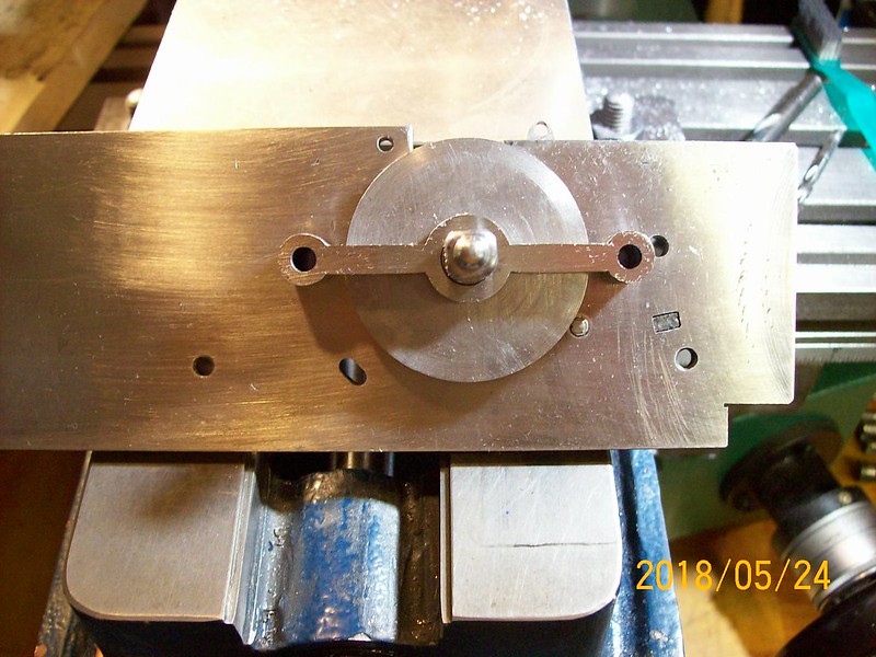
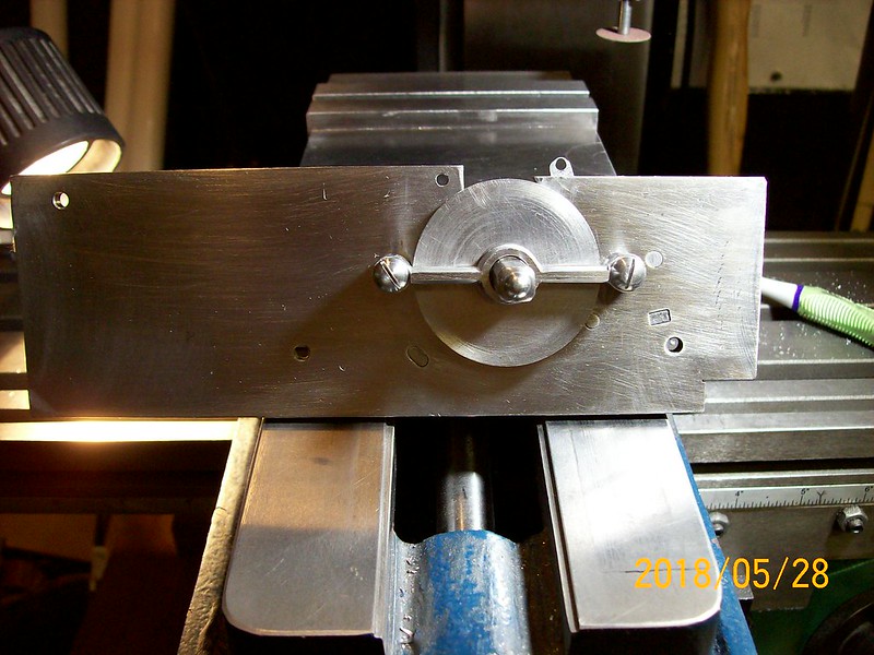
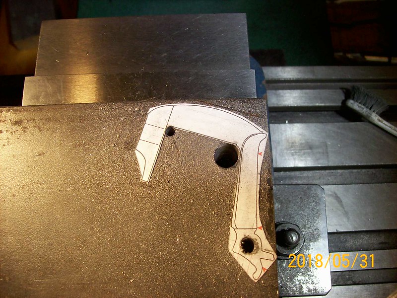
Support top smoothed out.
100_0596

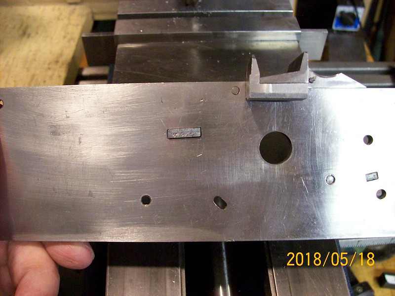
later, Mike (click on the photos & they'll enlarge at flickr)
 
Cutting the hooks on the mainspring. Made a sandwich with a piece of sacrificial aluminum and a piece of brass spacer in the back to hold things in place.
100_0602

When I compressed the spring I discovered there's too much curve in the lower arm! - tomorrow afternoon it goes under the torch again for some straightening. I spent some time making parts to clamp the spring to the underside of my drilling jig & will heat it there so it doesn't twist.
100_0601

later, Mike
 
https://flic.kr/p/JQ91YS
Well, the mainspring is somewhat straighter after heating & messing with it several times. I'll have to compress the spring more and see how the bridle fits. I have the feeling that the lower arm is bending because the spring is not hardened yet. Any spring gurus in the audience?

Mike
 
Haven't done much work the last few days. Have thinned down the lower mainspring arm, but still needs reshaping (needs more curve). Installed a small spring to close the pan cover. The spring is held in place by a tight thru mortise and by spring pressure on the pan arm. The pan cover spring needs to be rehardened as it is too weak right now. You can see the mainspring is also too straight now by the lower bridle arm; one step forward, two steps back..........
https://flic.kr/p/25XY4f3

Mike
 
I'm really amazed at the amount of machining that needs to be done. I knew these locks were complex...but holy cow! :shocked2: What craftsmanship :thumbsup: :hatsoff:
 
Cruzatte said:
I'm really amazed at the amount of machining that needs to be done. I knew these locks were complex...but holy cow! :shocked2: What craftsmanship :thumbsup: :hatsoff:

Most of the wheellock could be made by file work, but I don't have the skill to do it so I machine it instead. Machining also requires you to think about how you are going to hold it when you cut it and how you are going to hold it for the next operation. I am just a hobby machinist with 3 semesters of junior college training to keep me out of trouble.

It is also be faster to cut & file to shape than to machine it. I have to keep reminding myself to saw away material first then machine it, because it is so much faster. I'm sure lock makers were a specialize trade, like barrel makers & stockers.

I haven't worked on the lock for a couple of days, getting caught up on yard work. I'm having cataract surgery tomorrow, so I won't be posting any progress for several days.
see ya later, Mike
 
Well cataract surgery went okay, hurt like sink, but I can work for a few hours before my eyes tire out.

I'm installing the other piece of the mainspring bracket/bearing box on the lockplate. This is the last piece that has a tab pierced thru the plate and peened over.
First photo shows the piece to be installed with the layout blue on the lockplate:
https://flic.kr/p/27dXVZb I used a hardened rod in the drill chuck to align (rotate) the lockplate against the existing mainspring bracket & then clamped the plate in place.

Drilling holes for the tab:
https://flic.kr/p/27dXW4u

Slotting the plate:
https://flic.kr/p/Kacb5h

Tab fits in the slot:
https://flic.kr/p/26cn54U

Lockplate clamped in a vise upside down. Squared the slot corners with needle file and fit the tab:
https://flic.kr/p/Kacb1E

Tab viewed from the front, the edges of the square hole are lightly chamfered before peening the tab:
https://flic.kr/p/27dXW25

Tab peened and cleaned up:
https://flic.kr/p/27dXVXs (it's like magic, ain't it)

Mainspring bracket drilled & tapped for a 10-24 screw for the sear arm:
https://flic.kr/p/HCYhbD

My eyes are blurry now, see you later. Mike
 
Spent the last few days making sear parts (2), screws for the sears and a sear spring. This is a view of the back of the lock with the 2 sears in place:
https://flic.kr/p/24FiNzs

View from the top:
https://flic.kr/p/24FiNvQ You can see the spring pushes down on the trigger sear and up on the sear arm. The spring material is only .027" thick, but is still too strong, I need to taper both arms. The trigger sear vertical arm will be trimmed to length later.

View of the front of the plate. There is a hole at 10 0'clock that is for the foot of the sear. The round foot sticks into the hole. The hole will have a ball bearing (.250") sitting in the hole and will match up with a divot hole in the back of the wheel & is suppose to hold the wheel in the cocked position. This is the method used in the Georg Lauber wheellock and is used in the Mendi wheellock also.
https://flic.kr/p/24FiNAE

That's all for now, Mike
 
Mike,

Pleases the surgery went well. Had both mine done some years ago.

Can't quite see how the sear works, just figuring it in my head...I have looked at photos of originals and they look the same, but can't see how the peg is withdrawn from the wheel..
 
RJDH said:
Can't quite see how the sear works, just figuring it in my head...I have looked at photos of originals and they look the same, but can't see how the peg is withdrawn from the wheel..

Pukka, here's a detail of the Lauber sear that uses the ball bearing to hold the wheel cocked:
https://flic.kr/p/27ofgWE
When you pull the trigger it releases pressure on the sear arm and the ball bearing retracts into the hole - wheel spins (hopefully). Hast du verstanden?

later, Mike
 
Making an outside wheel bearing today. Most times the wheel bearing is just a small tab that stabilizes the wheel. The bearing I'm making spans the wheel and was used on some military wheellocks. First photo shows the steel block drilled for 2 No.8 screws and boring the center of the block for the bearing that is on the spindle:
https://flic.kr/p/24KaumW You can see layout numbers written on the mill vise (saw it on you-tube), just remove it with lacquer thinner.

Spindle bearing fits into the wheel bearing:
https://flic.kr/p/KmVqUN

Wheel bearing marked out and rough cut to size:
https://flic.kr/p/24KaukJ

Cutting radius on the part. Saw this on you-tube, you use the drill bit to swing the part around and clamp into place with the vise. You set the height of the end mill and cut to size. I usually do 1 or more rough cuts before cutting the final size of the part.
https://flic.kr/p/24Kauj1

Here's the part in place. Still needs final fitting and filing, make the screws and drill & tap the plate.
https://flic.kr/p/KmVqS3

View of the part from the front:
https://flic.kr/p/27uRfKe

see ya later, Mike
 
Here's a photo of the lock I'm loosely trying to copy:
https://flic.kr/p/26p1Swd
You'll note that I have much more clearance from the wheel (spacing of the screw bolsters) than the original. I have about .082" on each side rather than the piece of paper clearance on the original. Those guys knew what they were doing 500 years ago.
 
So the wheel bearing needs to go on a diet. First we cut a filing jig on the lathe:
https://flic.kr/p/26rbCu3 The filing jig is for the center of the wheel bearing only

Then we file for hours.... I made a second filing jig because the first one was too short. Photo of the filing jig on the wheel bearing:
https://flic.kr/p/26ake1Z The filing jig is sacrificial, it's not hardened.

Wheel bearing looks better now:
https://flic.kr/p/27x1NkZ

Tomorrow we make some more screws! (geez i can hardly wait?) Mike
 
A solemn Memorial Day to you.

I remade the wheel bearing. I had too many filing errors and didn't like the clearance of the bearing from the wheel.
So here is the new part mounted on the the lockplate:
https://flic.kr/p/26fMUZ4
I still have filing to do on the part, but I think it looks a little better.

Here's an edge view:
https://flic.kr/p/27y7qx3 looks like I need to cut another couple of threads on the mounting screws.

see ya later, Mike
 
Working on making the cock today. Had to go to a steel supplier to find 3/4" plate material. I buy cut-off pieces and they raised their prices since I was last there because of the trade imbalance - in went into effect today (it will be interesting to see if they raise them again). It's $1/lb. now, use to be 75 cents, but glad to find scraps that I can use.

Here's a photo of the cock glued onto the plate & some holes radius holes drilled and a pivot hole for a screw:
https://flic.kr/p/KAnrxb
The drawing of the cock comes from this web site: http://feuerwaffen.ch/index.htm . There is a pdf file of a 1600 military wheellock with metric dimensions that I reduced to fit this lock.

Here's the part cut out and profiling started:
https://flic.kr/p/KAnrzW

I got a little further than the last photo but it's not significant. More tomorrow, Mike
 

Latest posts

Back
Top