UNITED .STATES PATENT OFFICE.
H. H. SIBLEY, OF THE UNITED STATES ARMY.
CONICAL TENT.
Specification of Letters Patent No. 14,740 dated April 22, 1856.
To whom it may concern:. '
Be it known that I, H. H. SIBLEY, United States Army, have invented a new and Improved Conical Tent; and I do hereby declare that the following is a full and exact description thereof, reference being had to the accompanying drawings and to the letters of reference marked thereon.
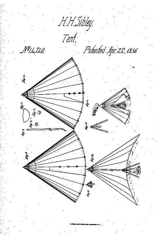
The tent is in shape the frustum of a cone ( as shown in Figures 1, 4 and 8) ; the base 18 feet. height 12 feet; the apex 1 ft. 6 inches (Fig. 1); at the apex, or opening at the top. The canvas is held in position by means of an iron ring or wooden hoop (Fig. 9); if the latter, it should be made of the best material of white oak, two inches wide and 1 inch thick. The canvas to be sewed strongly over it and reinforced for 12 or 18 inches down (Fig. 8). Eight holes (dots in Fig. 9) are made around the circumference, through which eight cords (Fig. 9) pass terminating in a wooden knob (Fig. 2), rounded at the top (Fig. 2) and flat at the bottom, three inches in diameter .and three inches thick, with a neck or throat (Fig. 2), to which the cords are fastened, the bottom or flat surface of the knob (Fig. 2) with a hole an inch in diameter and an inch and a half deep (hole Fig. 2), or, in place of this knob an Iron circular plate slightly cupped with a hole in the center, for a spike in the end of the pole to pass through (Fig 2) and with eight holes in the perimeter, for the cords to pass through and be secured (Fig. 3) .
The doorway is 9 feet 2 inches, measured along out of the elements and closed by means of a flap of triangular shape 8 inches at the top, and the ordinary width of canvas at bottom, the straight edge of which, and the upper lap are secured fast, respectively, to one side of the doorway, and across the top-the lower point to have a loop by which it is fastened to one of the tent pins (Fig. 1). To secure a more perfect ventilation, an opening is made in the seam opposite the doorway five feet measured along the seam from the ground up (Fig. 4) ; the half door or opening admits of the wall being raised at the rear of the tent sufficient for all purposes of draft and ventilation. . The fastenings of this door may be best described and understood by assimilating it to the opening in a pair of pantaloons, instead of buttons. Eyelet holes (Fig. 4) are made on the two edges .and they. are brought together and secured by means of a cord (Fig. 4). At proper points on the tent wall, loops should be strongly sewed on, for the purpose of fastening up the canvas of the half door when open (or instead of this opening substitute a doorway in all respects like the one in front, described above (Fig. 4).
The tent is pitched by means of a single pole (Fig. 5) arranged with an iron tripod (Fig. 6) so constructed as that the legs shall work upon strong hinges (Fig. 6) and fold against the pole, to which they are fastened by means of a cord, attached to the pole through a hole (Fig. 5). Each leg is made in the shape of a trough or half cylinder, so that they shall not only fit snugly around the pole, when folded up, but to give them more strength. The tripod to be furnished with a socket three inches deep into which the lower end of the pole fits snugly and is fastened by means of a rivet (Fig. 6), or for the socket, substitute a swivel ring or plate of iron, with a hole through which the end of the pole shod with iron may rest upon a shoulder (Figs. 5 and 6). The legs are 4 ft. 6 inches long, 2 inches wide and ¼ inch thick (Fig. 6). The pole (Fig. 5) from 2 1/2 to 3 inches thick and may be in length half the diameter of the tent base to facilitate the pitching; with an iron pin in the top and a staple at the bottom (Fig. 5) or a hook and chain for hanging a camp kettle or other cooking utensils for boiling. Each leg to have two or more holes for suspending meats for roasting (Fig. 6).
When pitched the space between the legs of the tripod (about 3 feet) is excavated about six inches deep, sloping to the center, and the earth taken out used to form a ridge around the outer edge of the hole to keep the fire, placed there, in position. Twenty four pins have been found amply sufficient for the ground fastening. To assist the escape of smoke in windy weather a triangular piece of canvas (Fig. 7) with an eyelet hole in each angle is fitted by an angle to the pin on the top of the pole, the other angles secured by means of cards to the tent pins (Figs. 7 and 8). To pitch the tent, the points of the four quarters are first secured, the pole is then inserted, the apex raised and the tripod adjusted, the remaining points then drawn taut. It is recommended that red chalk marks, define the three quarters of the tent while the door marks the fourth, to facilitate pitching.
This tent will hold comfortably 20 men with arms and equipments, has the advantage of warmth in cold weather and for cooking in rainy weather, is more .perfectly ventilated and comparatively lighter than any now. known.
Having described my tent as above, I will state generally what I wish to cover by the receipt of Letters Patent.
1. So constructing the tripod or its equivalent device attached to a single pole as to admit of easily building a fire, for the purposes set forth.
2. Constructing the tent as described with its hood or cowl, in combination with the door and half door, or opening to effect ventilation and the escape of smoke.
H. H. SIBLEY.
Witnesses :
L. SIMONS,
R. H. MONSON.