• This community needs YOUR help today. We rely 100% on Supporting Memberships to fund our efforts. With the ever increasing fees of everything, we need help. We need more Supporting Members, today. Please invest back into this community. I will ship a few decals too in addition to all the account perks you get.


    Sign up here: https://www.muzzleloadingforum.com/account/upgrades
  • Friends, our 2nd Amendment rights are always under attack and the NRA has been a constant for decades in helping fight that fight.

    We have partnered with the NRA to offer you a discount on membership and Muzzleloading Forum gets a small percentage too of each membership, so you are supporting both the NRA and us.

    Use this link to sign up please; https://membership.nra.org/recruiters/join/XR045103

Making a Pattern 1756 Long Land British Musket

Muzzleloading Forum

Help Support Muzzleloading Forum:

This site may earn a commission from merchant affiliate links, including eBay, Amazon, and others.
Hi,
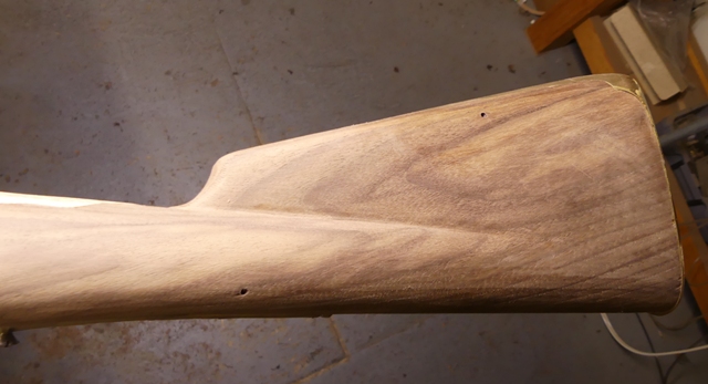
Holiday visiting and activities reduced my shop time. We finally got back to the Bess. Maria began inletting the butt plate while I began building the lock. The first step was cleaning up all the edges of the butt plate and flattening any that touched the wood as well as filing draft on the edges of the return. The casting was very good and clean but it also was hard for brass. It needed a lot of annealing to eliminate the springiness and resistance to filing. The machine inletting was off center, which we could mostly but not completely correct. It is minor and no one will notice in the end.
12umXrO.jpg


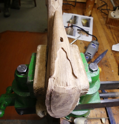
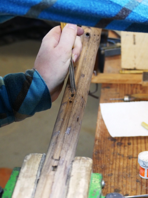
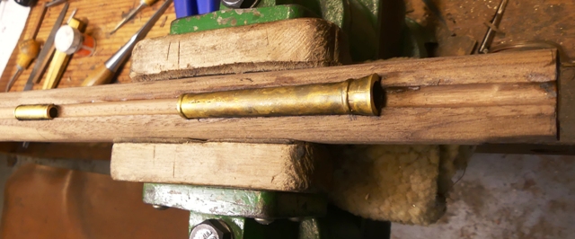
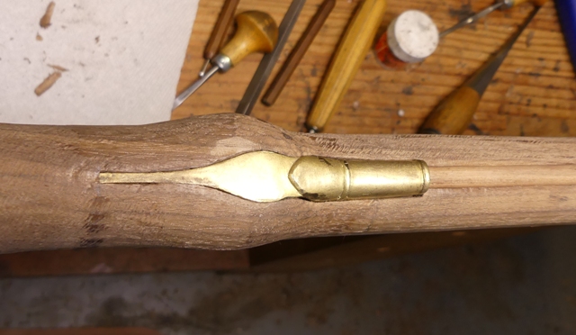
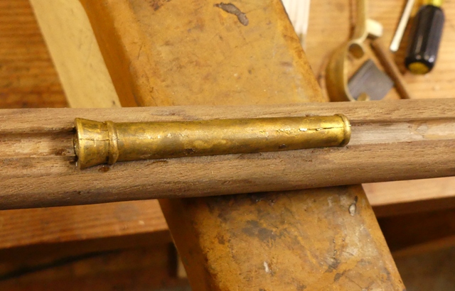
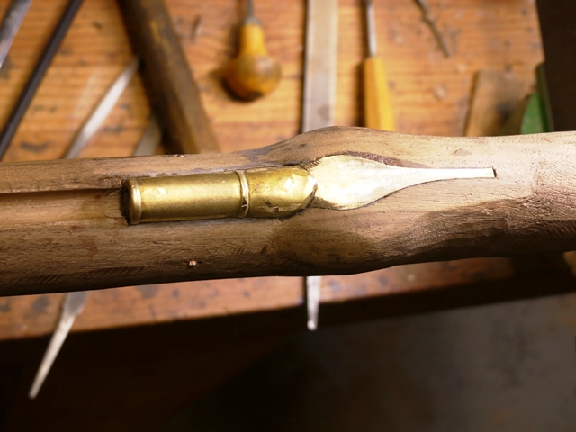
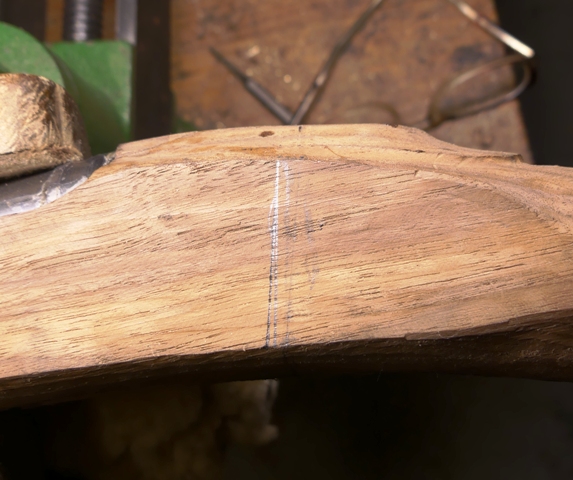
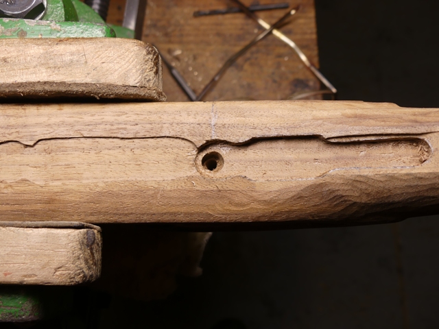
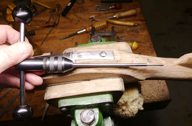
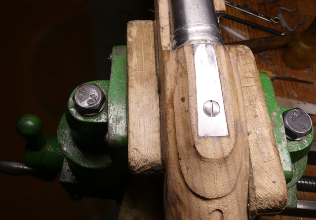
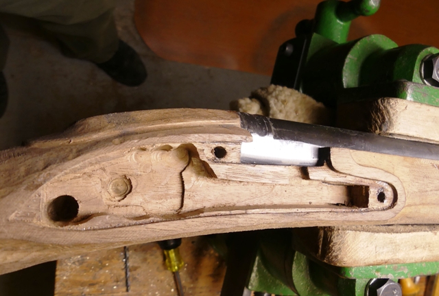
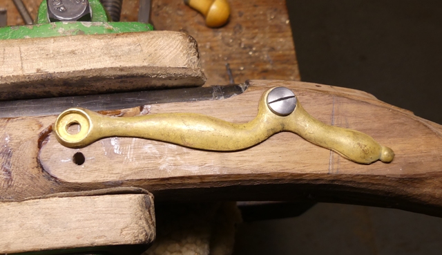
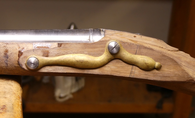
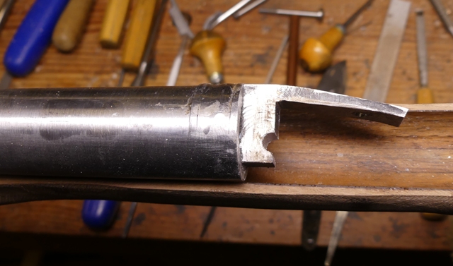
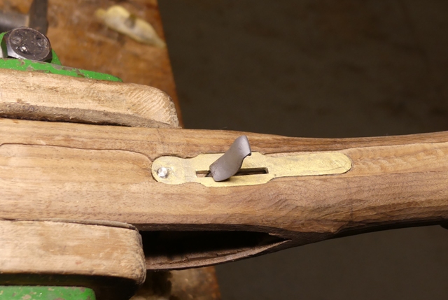
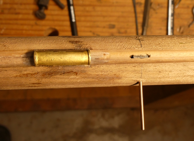
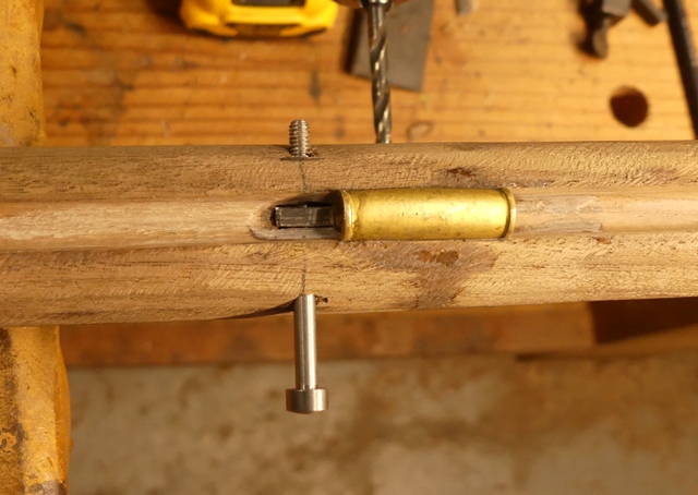
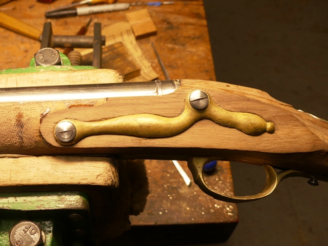
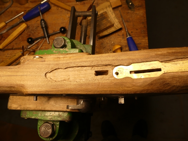
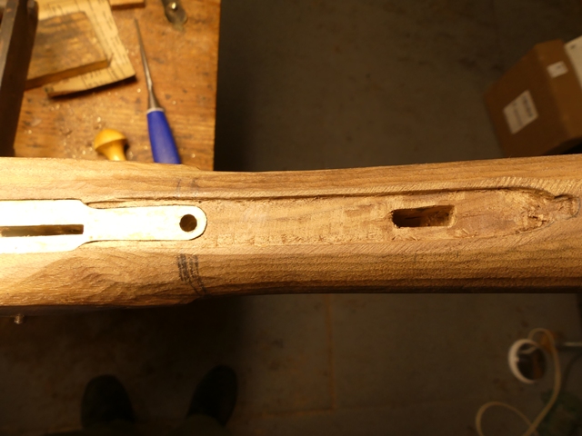
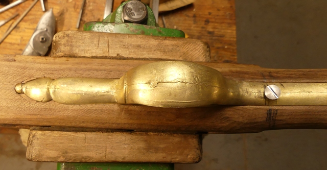
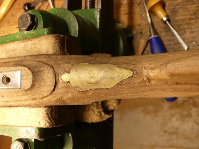
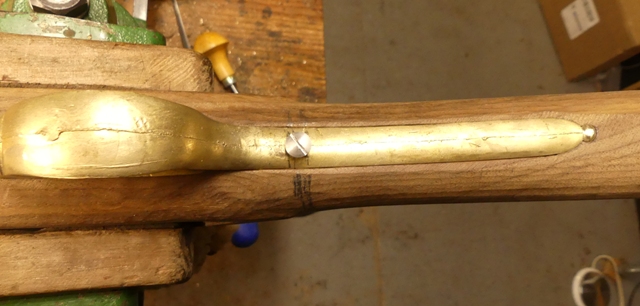
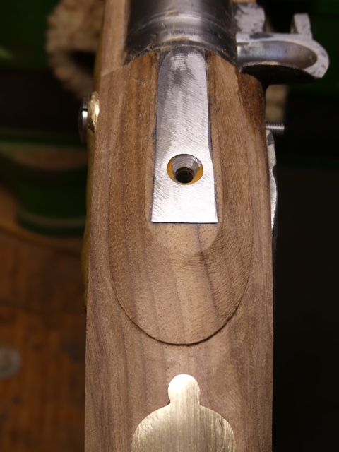
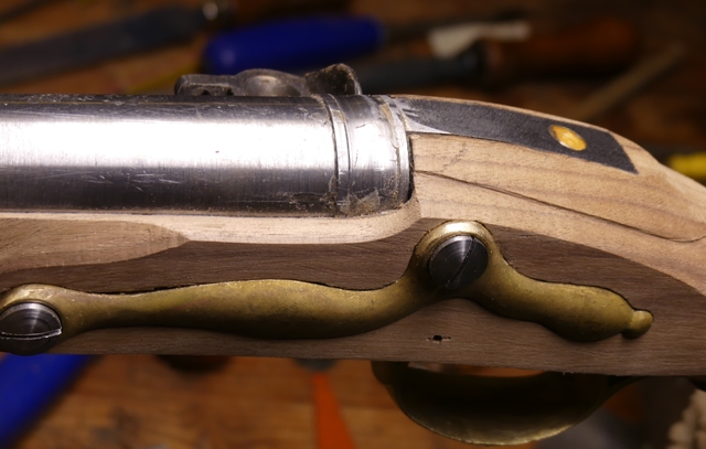
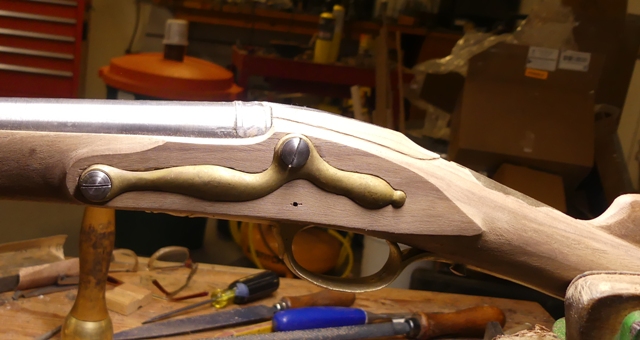
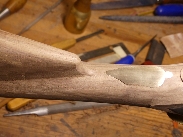
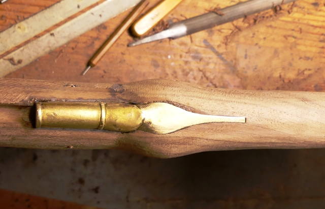
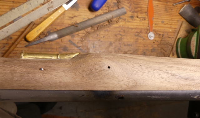
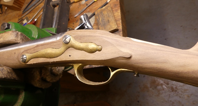
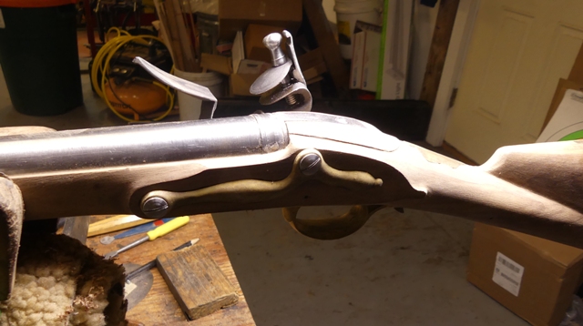
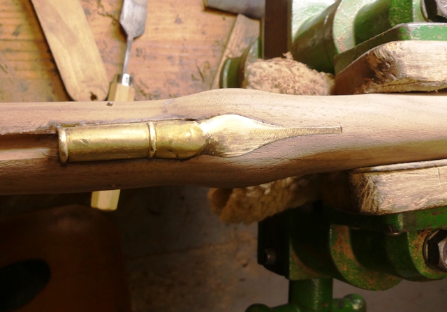
The first step is to locate and inlet the slot for the forward lug. This does not have to be precise and because the plate will move around a bit during inletting, making the slot a little oversized in all dimensions is a good thing to do, with the emphasis on a " little oversized". You have to inlet this plate straight down unlike later Bess pattern butt plates. So rask away most of the extra wood at the end of the stock allowing the butt face of the plate to rest close to the stock. That stock and face of the plate should be almost straight. Then bend the front of the tang from the under lug forward up so it allows the tang behind it to be partially inlet without the front interfering. Set the buttplate down into the stock and trace the rear 2/3s of the tang on the wood. Stab in that outline and remove the interior wood until the plate sets down into the mortice. Now check how the face plate meets the stock and the rear of the tang. When they are well fitted, bend the forward part of the tang down level with the rest of the butt plate, trace it on the wood, and inlet the mortise. Here is our end result and I doubt you can find a better job.
WcqmURk.jpg

BKMCbcL.jpg


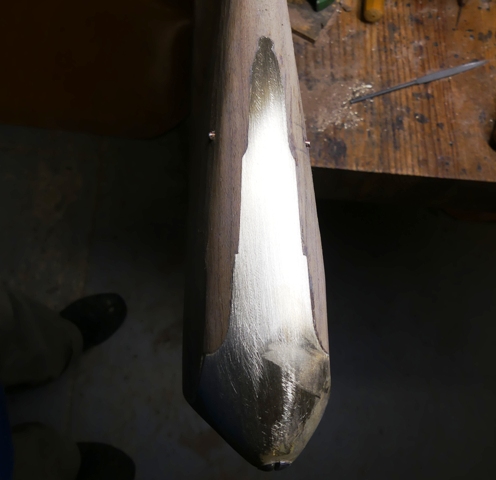
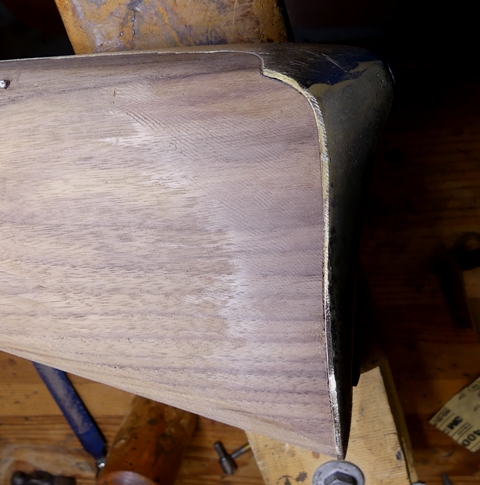
However, I make that brag with one huge caveat. The black walnut used on this stock is very difficult to work. It chips, collapses, and shreds with minor pressure. It is almost impossible to do detailed inletting. Consequently, I added stained AcraGlas along all the edges of the tang. The inletting we did was precise but shredded and cracking wood bordered much of the mortise ready to be torn out. So I smeared AcraGlas on the edges of the mortice and over the cracks in the stock along the edges of the mortise. The butt plate fit tight and pressed most of the epoxy out but also into the wood along the edges. That solved the problem and strengthened the entire mortise, but most importantly, the wood adjacent to the butt plate. I am afraid we will have to do the same for the trigger guard.

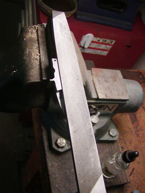
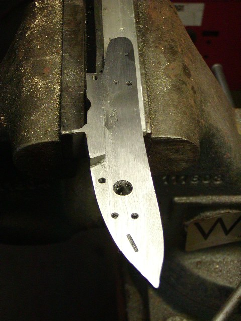
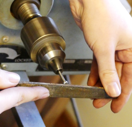
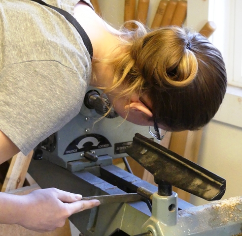
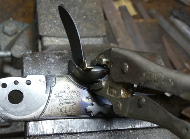
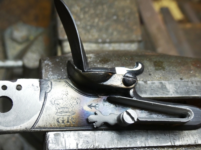
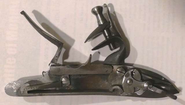
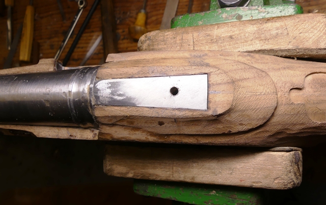
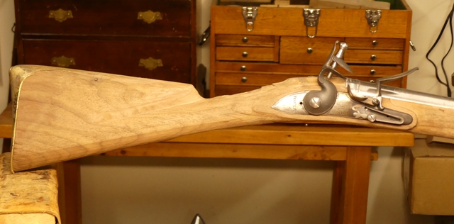
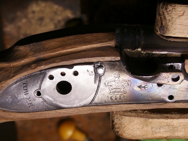
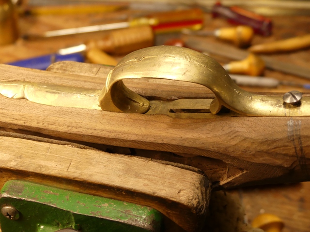
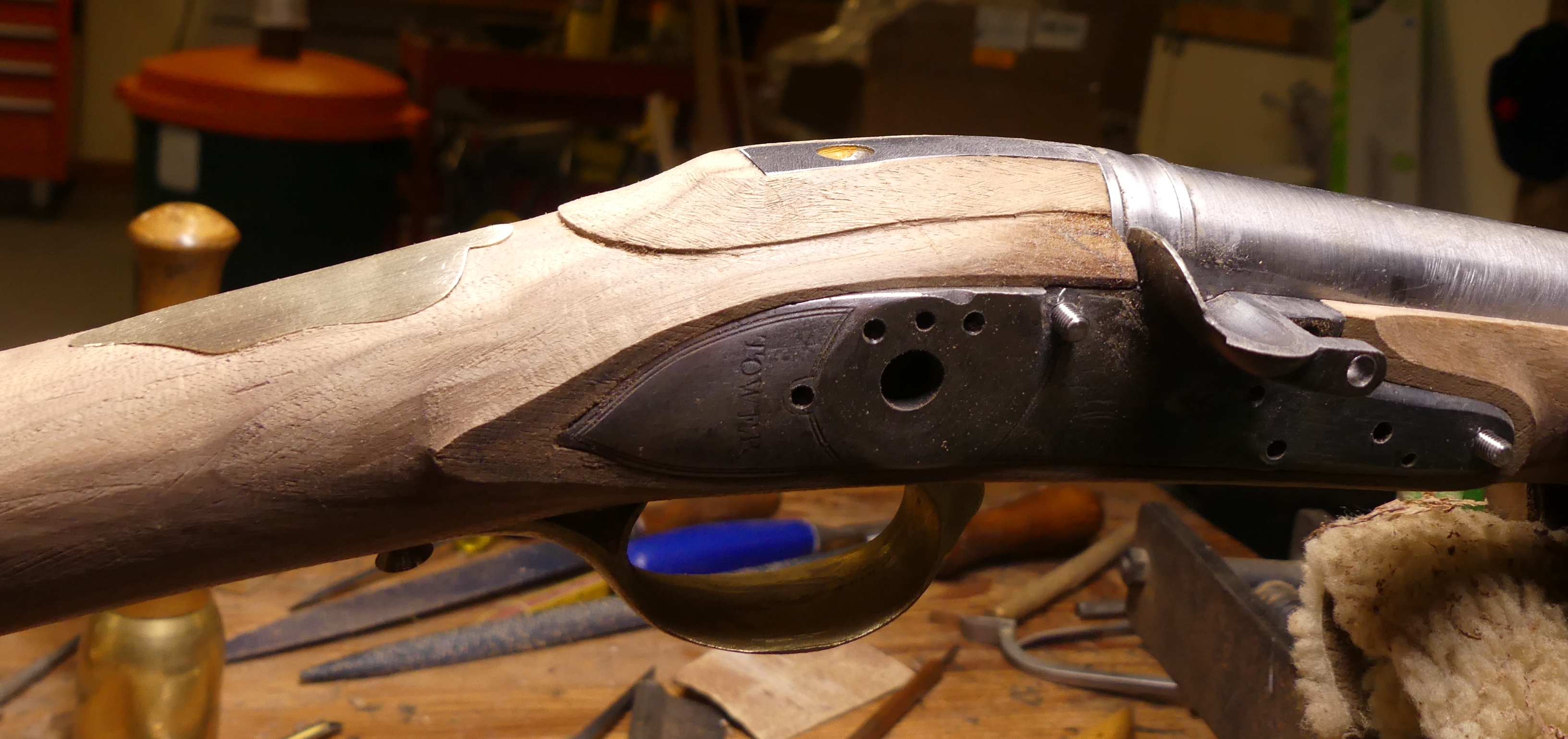
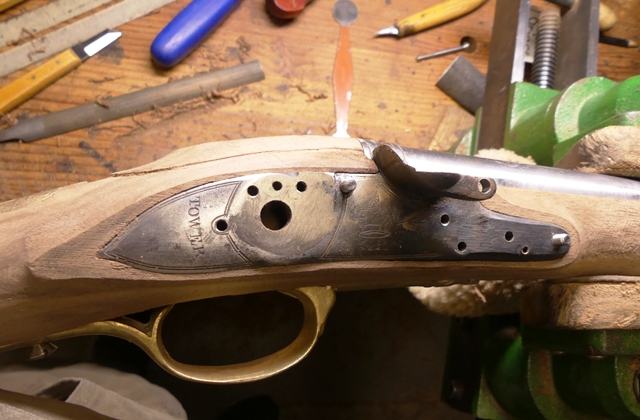
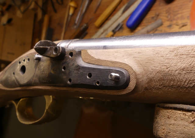
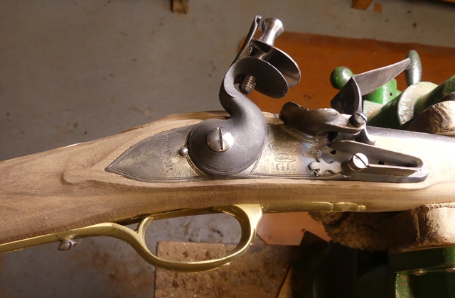
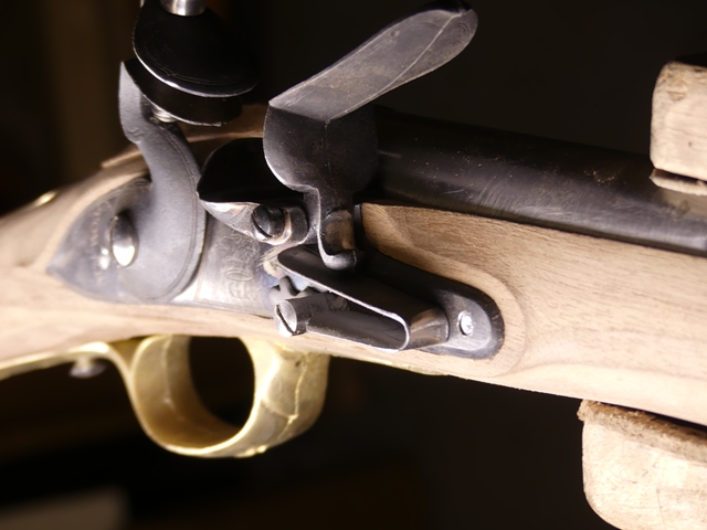
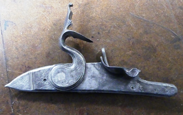
We started building the lock. I trued up the tumbler on my lathe so the round post for the flint cock and post for the bridle were perfectly concentric and true. I also trued up the sides of the tumbler. Once that is done, I accurately measure the diameter of the tumbler post and drill a slightly undersized hole for it through the lock plate. I use the TRS witness mark to center that hole. Then I file or stone the hole until the tumbler begins to fit tightly. I fit the flint cock on the tumbler and then use it to rotate the tumble in the lock plate to lap it into place. I smear valve grinding compound and paraffin oil on the tumbler post and then place it in the plate, attach the flint cock, and rotate it back and forth until it fits precisely and smoothly in the lock plate.
xa6JiKW.jpg


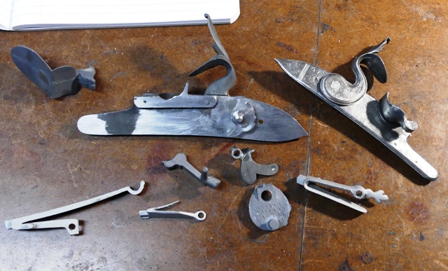
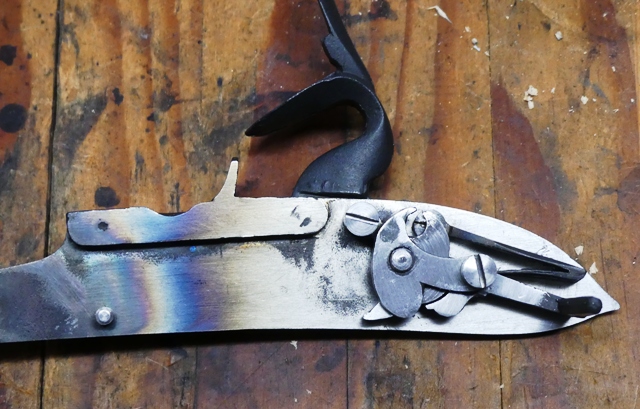
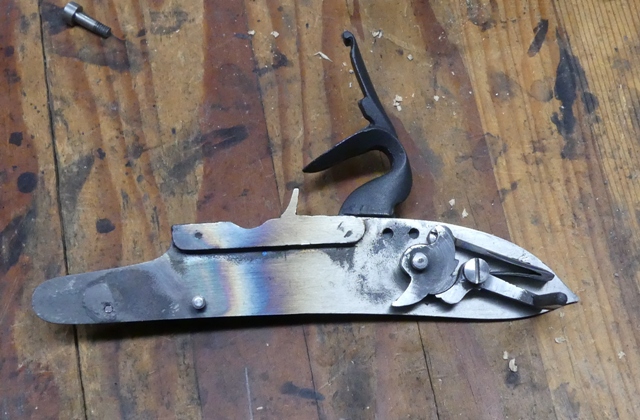
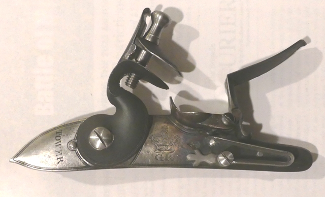
While working on the Bess, Maria is also working on building a very fine Joseph Griffin English lock from castings by Blackley in the UK.
sPamFmX.jpg


We have a very busy shop.

dave
 
Hi,
We are back at work after the holidays. I need to back track a little on the lock. TRS lock parts are generally good quality but often you need to take care of some issues. Often the lock plate is not flat inside and some will be slightly warped from the casting process. The first thing to do is flatten the inside of the plate and remove any warp. That usually requires heating the plate red hot and beating it straight with a hammer. Then after cooling, use a large flat file to file the inside surface flat. I use single cut lathe files. The photos show an L&R lock but you get the idea.
hYz2hSy.jpg

ZJyvr40.jpg


Also flatten and true up the inner side of the bolster that fits against the barrel. I previously described fitting the tumbler to the plate. After that, I drill the hole for the sear screw indicated by the cast in engraving. This is different from building other locks in which I drill the tumbler hole through the bridle first. With TRS Brown Bess parts, the sear screw needs to fit into the outside engraving so it goes first, although you can wipe out that engraving and act as if the lock was any other. Next, I drill the sear screw hole through the bridle. I simply centered the hole in the back lobe of the bridle. I always drill undersized holes and then correct any position problems by filing and then drilling with the correct sized drill. I make an extra long sear screw so I can attach the bridle to the plate without the pin and bridle holes drilled. Here is Maria making screws on a wood lathe using files and then dies.
eBAOWnF.jpg

GIBRVvF.jpg


I move the bridle about while inserting a 3/8" - 1/8" centering countersink drill bit in the tumbler hole to make sure where I mark the hole for the bridle pin allows plenty of bridle thickness around the tumbler spindle hole. I mark the pin location and then drill it, find the bridle screw location and then drill and tap that hole. With the bridle and sear screws attaching the bridle to the plate, I use my drill press and the 3/8"-1/8" counterbore inserted in the tumbler hole in the lock plate to drill the tumbler spindle hole. Then I drill a larger hole in the bridle to fit the tumbler spindle. I file and redrill the holes to get the correct fit much the way they did it in the 18th century. They did not have fancy drilling and milling machines, rather they relied on jigs and skill, which I do as well. Next I file and drill the sear to fit and then drill and tap the hole for the sear spring. I clean up the cast springs enough to fit them but do not harden and temper them until later. I cut the slot for the tab on the sear spring first with a die sinker's chisel and then finish it with a thin cylindrical diamond bit in a Dremel. I want the end of the lower leaf of sear spring to reach right up against the boss on the sear for the sear screw.
G9huGr0.jpg

Without the bridle, you can see how precisely the sear fits against the tumbler.
ruSAAv1.jpg


I fit the flint cock on the tumbler using files such that it must be pressed into place with a vise. For this parts set, the tumbler post was too short such that the shoulder at the base of the square post was below the surface of the lock plate. That is unacceptable and reminiscent of India-made guns. I had to thin the lock plate inside and out to make sure that shoulder protruded above the lock plate. I drilled and tapped the hole for the tumbler screw. Drill that hole at least 3/8" deep and 1/2" is not too deep. Be very careful here because it is a blind hole requiring a bottoming tap. Now you have the entire internal mechanism installed minus the main spring. Make sure the head of the sear spring screw clears the curved tab on the tumbler and it small enough diameter to allow the shoulder on the flint cock to contact the lock plate bolster when the cock is at rest. You can see in this photo, the screw head is stopping the tumbler before the shoulder contacts the plate.
G9huGr0.jpg


Now it is time to install the top jaw and top jaw screw. Clean up the components a bit and get rid of the marks on the jaws of the cock and top jaw indicating where the teeth were. File and grind them flat as you freshly should cut them later. File the cock and top jaw so they fit together. The cock should have a groove for a little tab on the top jaw, holding it in alignment. My cast flint cock did not have any groove so I ground it in place using my Dremel and a diamond bit. I also filed the back edge of the top jaw to fit the cock as well as shaping the tab. When fitted, mark the position of the top jaw screw so it is fairly tight to the back of the flint cock, drill and tap it. Drill out the top jaw to fit the 5/16"-18 top jaw screw. You want the top jaw to slide along the flint cock without a lot of slop.

Now install the frizzen and feather spring. Clean up the feather spring and then use the witness mark on the outside of the lock plate to locate and drill the spring pin hole. Now the spring will fit down flat on the lock plate and you can accurately mark the location of the feather spring screw hole. Drill and tap it. Next install the frizzen. Clean it up as well as the pan and pan bridle. Next, file the top of the pan and bottom of the frizzen so they mate really closely. Then clamp them in place with a long nosed vice grips, and drill the tap sized hole through the lock bridle, frizzen and lock bolster. I use my drill press for this. Then, and this is a real time saver, install the frizzen and place a shim at the back edge of the frizzen.
ETCZOc6.jpg

Reattach the frizzen with the vice grips and then drill the clearance hole for the frizzen screw through the bridal and frizzen but not into the bolster. Then tap the bolster for the screw threads using the pan bridle as a guide. What happens is you will find that the frizzen still sits down on the pan as fit, whereas if you did not use the shim, you would be refitting the frizzen to the pan.
CeRmDMh.jpg

Finally, fit the mainspring. Often it needs to be thinned a little because during th tumbler truing process, the tumbler is thinned and the end of the hook on the spring no longer clears the bridle. Don't fret, just thin the spring. I drill the hole for the spring pin first, and then fit the spring and drill and tap the hole for the spring screw. I want the tip of the hook on the spring to ride up the tumbler such that it is positioned in the instep of the tumbler at full cock. That will provide superior performance. I will discuss those details later in the thread.
xE5oHYW.jpg

Z8ubyZ8.jpg


More to come,

dave
Would it be safe to say that this lock is much finer in fit and function than were most originals, if not all?
 
Thanks Dave. I should have asked if it will be... but at any rate, it'll be first rate.
Hi Bob,
It would pass British ordnance inspection and be quite representative of the work those 18th century makers did. We moderns have such a distorted idea of the past. We cannot conceive of a world where everything is hand made and cannot conceive of the power of skill relative to the precision of machines. We forget that the greatest performing flintlocks ever made were before the machine era. Those locks are still superior to anything made today even by CNC assisted machining. Even the most mundane, generic English sporting gun locks during the flint era are usually better than anything produced today.

dave
The first lead screw for a metal lathe was hand laid out, cut and filed. Yes, they were capable of very precise work, stunningly so.
 
Hi,
Maria and I got the pipes inlet. All was fine except the walnut was horribly chippy and stringy. The 3 front pipes went in fine but the mortise edges are very weak because the wood is not dense. We will take care of that. The rear pipe was a nightmare. The machine inletting was badly off such that we could not fit the pipe without gaps. Don't file off that little tooth at the end of the rear pipe, it anchors the finial into the stock preventing it from popping up above the wood. The machine inlet was sloppy and would not allow the pipe to be moved enough to the rear to prevent gaps between the wood and pipe at the step. If you moved it back, there was a gap at the front of the pipe. If TRS allows custom ordering with respect to their stocks, I recommend you ask to have the barrel inlet and the stock profiled, and nothing more. No inletting of any other components. None. Not even the ramrod. I got the rear pipe in and closed some of the gaps by annealing the brass and then peening the edges to expand them. It worked to a point but I am not totally happy with the results.

2jFGrPS.jpg

pN9XUuE.jpg

WgR941N.jpg


It will require some bedding in AcraGlas to strengthen the mortise and fill some gaps. The good news is none of that will be noticeable after I am done. I am pretty good at fixing this stuff but I wish I did not need to be.

dave
 
Hi Jim,
It is a beautiful lock! Maria did a great job on it. It is completely assembled, however, we have not done any final polishing or heat treating yet. She will post photos of it in her "Officer's Fusil" thread on ALR. The Bess lock above also needs polishing and heat treating, which will happen soon. I sure admire your machined locks. These locks from castings can be good but they are a lot of work to clean up, true up, and polish up.

dave
 
Hi,
I fixed and bedded the pipe inlets today. For all but the rear pipe, it was just to strengthen the mortise. The AcraGlas went on thin and was pressed hard into the edges of the mortises. When the stock is finished, the bedding will be invisible.
ImZzMl7.jpg


The rear pipe was another story. There were a lot of problems with it. The machined mortise was too deep so the hole in the pipe did not line up with the ramrod hole. The pipe could not be moved further back to cover some a gap at the step because that would open up other gaps and create another at the front of the pipe. So I used a combination of peening the edges of the pipe's tang to fill some space, moving the pipe to the rear, and filling space and remaining gaps with AcraGlas. It came out OK.
t0bb8l4.jpg


However, there is still a hairline gap at the step on one side. It is not noticeable but I am concerned it could get worse as the wood ages and changes with humidity and temperature. So later on, I am going to solder a tiny sliver of brass in place to fill the little void. It will be a permanent fix and invisible.

I installed the barrel tang screw and trigger plate. The machine inletting for the trigger plate is off center from the machine inletting for the trigger guard. Fortunately, there is enough extra depth in the stock at the breech such that I can eventually wipe out the shallow mortise for the front of the guard. The rear mortise is deeper so I had to make sure the trigger plate was centered on the rear extension. It wasn't but I could make it so by inletting. With any pre-carved stock, and especially TRS stocks, never, ever assume the machine inletting is centered or marks the actual center of the stock. Always, always, always check. It will save a lot of tears. Drilling for the tang bolt, I don't fuss with a lot of drilling jigs. First I inlet the trigger plate and pushed the inletting as far to the side plate side as I could to offset the poor machine mortise but without creating gaps. Then I drill a tap drill sized hole in the barrel tang and make sure that hole is perpendicular to the surface of the tang. I drew guidelines on the side of the stock to help me. I drill down about halfway through the stock. Then I locate where the bolt should come out on the bottom of the stock within the receiving boss of the trigger plate. I drill up from the bottom, using my guidelines until I meet the top hole. Then I use a larger drill to clean up and connect the holes. After that, I drill down from the top with a clearance drill for the tang bolt until I touch the trigger plate. I hold the trigger plate in the stock with a c-clamp and drill it for the 10-32 tang bolt. Then I use a long pulley tap to thread the hole.
s3bZvDZ.jpg

yKMZ0WH.jpg

aUS1SxB.jpg

ehJNmiW.jpg


After the hole in the trigger plate is tapped, I counter bor the screw head in the barrel tang. I drill down with a "U" sized drill into the barrel tang until the enlarged hole has very shallow vertical side walls. Then I use a counter sink to contour the bottom of the hole to match the counter sink angle of the tang bolt. Next, I flatten the edges of the screw head slightly turning it in my lathe so it fits precisely into the counter bored hole in the barrel tang.
kVBxij1.jpg


So here is where we are. The next task is to fully inlet the lock. It is starting to look like a Bess.
MY0eFrr.jpg

vdRNgUW.jpg

lBsQuYa.jpg


dave
 
Hi Bob,
It would pass British ordnance inspection and be quite representative of the work those 18th century makers did. We moderns have such a distorted idea of the past. We cannot conceive of a world where everything is hand made and cannot conceive of the power of skill relative to the precision of machines. We forget that the greatest performing flintlocks ever made were before the machine era. Those locks are still superior to anything made today even by CNC assisted machining. Even the most mundane, generic English sporting gun locks during the flint era are usually better than anything produced today.

dave
The only other thing I might add is that the grade of lock makes an enormous impact on quality. Those designed for export are considerably poorer in quality. Some are pretty awful. As a whole, locks we find on original longrifles made here are probably mediocre at best
 
Hi,
I fixed and bedded the pipe inlets today. For all but the rear pipe, it was just to strengthen the mortise. The AcraGlas went on thin and was pressed hard into the edges of the mortises. When the stock is finished, the bedding will be invisible.
ImZzMl7.jpg


The rear pipe was another story. There were a lot of problems with it. The machined mortise was too deep so the hole in the pipe did not line up with the ramrod hole. The pipe could not be moved further back to cover some a gap at the step because that would open up other gaps and create another at the front of the pipe. So I used a combination of peening the edges of the pipe's tang to fill some space, moving the pipe to the rear, and filling space and remaining gaps with AcraGlas. It came out OK.
t0bb8l4.jpg


However, there is still a hairline gap at the step on one side. It is not noticeable but I am concerned it could get worse as the wood ages and changes with humidity and temperature. So later on, I am going to solder a tiny sliver of brass in place to fill the little void. It will be a permanent fix and invisible.

I installed the barrel tang screw and trigger plate. The machine inletting for the trigger plate is off center from the machine inletting for the trigger guard. Fortunately, there is enough extra depth in the stock at the breech such that I can eventually wipe out the shallow mortise for the front of the guard. The rear mortise is deeper so I had to make sure the trigger plate was centered on the rear extension. It wasn't but I could make it so by inletting. With any pre-carved stock, and especially TRS stocks, never, ever assume the machine inletting is centered or marks the actual center of the stock. Always, always, always check. It will save a lot of tears. Drilling for the tang bolt, I don't fuss with a lot of drilling jigs. First I inlet the trigger plate and pushed the inletting as far to the side plate side as I could to offset the poor machine mortise but without creating gaps. Then I drill a tap drill sized hole in the barrel tang and make sure that hole is perpendicular to the surface of the tang. I drew guidelines on the side of the stock to help me. I drill down about halfway through the stock. Then I locate where the bolt should come out on the bottom of the stock within the receiving boss of the trigger plate. I drill up from the bottom, using my guidelines until I meet the top hole. Then I use a larger drill to clean up and connect the holes. After that, I drill down from the top with a clearance drill for the tang bolt until I touch the trigger plate. I hold the trigger plate in the stock with a c-clamp and drill it for the 10-32 tang bolt. Then I use a long pulley tap to thread the hole.
s3bZvDZ.jpg

yKMZ0WH.jpg

aUS1SxB.jpg

ehJNmiW.jpg


After the hole in the trigger plate is tapped, I counter bor the screw head in the barrel tang. I drill down with a "U" sized drill into the barrel tang until the enlarged hole has very shallow vertical side walls. Then I use a counter sink to contour the bottom of the hole to match the counter sink angle of the tang bolt. Next, I flatten the edges of the screw head slightly turning it in my lathe so it fits precisely into the counter bored hole in the barrel tang.
kVBxij1.jpg


So here is where we are. The next task is to fully inlet the lock. It is starting to look like a Bess.
MY0eFrr.jpg

vdRNgUW.jpg

lBsQuYa.jpg


dave
Very nice work Dave great workmanship alaround .👍
 
Hi,
The lock is fully inlet. The machine inletting ruined any chances that the mortise would match the quality of work produced by the Tower in the 18th century. The routing for the tumbler was sloppy and ruined any precision, However, it cleaned up pretty well but just not as clean and precise as the originals. The hole for the sear was badly positioned and needed to be extended toward the rear.

LXz6a1i.jpg


Next I installed the lock bolts and prepared the side plate for inletting. The side plate is a little undersized probably from casting shrinkage. Not a big deal but still requiring adjustments. The rear lock bolt should be located to fit inside the lock engraving in front of the flint cock as shown.
MskCMjm.jpg


I locate that hole, center punch it, and then drill a tap sized hole through the plate and bolster using my drill press. Then I install the plate in the stock, and use that long hole to guide the tap drill while drilling through the stock. Next I drill through the stock with a clearance sized bit. Then I tap the hole in the plate through the stock with a pulley tap. Next I clean up the sprue and flashing on the side plate, and drill and file the bolt holes in the plate. I install the rear lock bolt through the plate and thread it into the lock plate. Using an adjustable square, I measure down from the top of the barrel channel to the center of the lock plate where I want the forward bolt to be. I then transfer that measurement to the other side of the stock, and rotate the side plate until its forward bolt hole intersects that measurement.
f3hYU8r.jpg


I punch that spot and drill halfway through the stock with a tap sized drill but only mark the inside of the lock plate with the drill. Then I correct that hole in the stock if it deviates much from center on the lock plate. I drill the tap hole in the lock plate where I want it but at or very close to the mark on the inside of the plate. Then I clean up the hole in the stock so it lines up the side plate hole with the lock plate. When that is done, I tap the lock plate for the forward bolt through the stock with my pulley tap. Now everything lines up properly.
aYvkSVE.jpg


A consequence of the large bolster on the breech plug and the deep threads is that the rear lock bolt hits the breech plug bolster. You could notch the breech plug to move the lock back or file the rear of the bolster so the bolt clears it. We just notch the bolster to clear the screw as was often done in the 18th century. If you do that, make the groove oversized for the bolt because if the fit is precise, the plug will act as a jack hammer hitting the bolt when the gun is fired risking damage to the stock.

GoHGLkX.jpg


Finally, I installed the trigger. Again there are issues with the parts set. The trigger slot in the trigger plate extends too far forward. If you mounted the trigger fully forward in the slot, it won't contact the sear of the lock. So the trigger has to be positioned further to the rear such that there is slot in front of the trigger.
JWhgzrA.jpg


I will eventually fill that slot with a strip of brass soldered in place.

More to come,

dave
 
Hi ArmorerRoy,
I don't know. They used iron wire and the original barrel pins I've seen seem to be fairly large perhaps about 3/32" which, is what I use. The pins for the pipes are definitely smaller.

dave
 
Hi,
A lot of final assembly stuff done yesterday and today. Our work was interrupted by a severe storm that passed through dropping wet heavy snow, rain and high winds. Fortunately, the shop dodged a bullet and did not have any damage or even a power outage. Vermont on the western side of the Green Mountains got hammered. We have another potentially severe storm coming in Friday night. Maria and I installed all the barrel lugs. I've posted several threads showing how we attach lugs on round barrels so I am not going to repeat that here. Because the lugs show in the bottom of the ramrod groove, it is easy to locate and drill the pin holes.
eMeOlYn.jpg


We just measure down to the lug in the ramrod groove, mark that depth on the side of the stock and draw a center line for the lug on the stock. We just eyeball that. Then we mark a hole with an awl a bit below the depth measurement of the top of the lug. I want the hole to be closer to the barrel than top of the lug. Then we just drill the 3/32" hole keeping the drill level and perpendicular to the stock by eye. That is how the 18th century Setter Uppers in the Tower of London did it. It is critical that the bolt and lug for the forward sling swivel is positioned so it overlaps the second ramrod pipe.
NXuqEsL.jpg


Next up was the sideplate. Maria cleaned up the edges and then inlet it. It came out well but there is one spot on the upper side near the front that chipped out. Actually, it just crumbled. We may inlet the plate a little deeper so that the chip is filed away but that decision comes later.
3Uu6SvJ.jpg


Then it was time for the trigger guard. The brass castings in this parts set are not soft yellow brass. They are some alloy typically used in investment casting that is stiffer and files harder. You have to anneal the trigger guard frequently to be able to push it into the contour of the stock. Moreover, the machined inlet for the guard on this stock was utterly useless. It was off center and too wide in places. Fortunately, the stock has sufficient extra wood on the bottom so I could completely rasp the machined mortise out of existence and do a proper inletting job. First, set the trigger plate down in the mortise deep enough to not interfere with the trigger guard. Cut the slots for the front and rear tabs on the guard so it can sit down on the wood. Don't worry about precision here because the guard will move as you inlet it, so give those slots some extra space to allow that movement. Inlet the front of the guard first. I want the guard positioned so the trigger is encompassed by the rear half of the guard bow, allowing plenty of finger space in front of the trigger.
bFMIpCs.jpg


You can see the lines of the machine mortise that don't fit the guard. They will disappear in the end. Once the front is in, work to the rear until the rear extension is in.
Phl9nzg.jpg


The guard should fit down in the stock so it tucks up against the trigger plate firmly (no gap) and the rear curl of the bow pushes the trigger plate down in the rear.
77eZBwT.jpg


5sYwXgc.jpg


Now comes the thumb plate. Clean up the edges and cut off the sprue on the bottom boss. I use my Dremel with a router bit to clear and deepen the hole in the stock for the boss on the underside of the plate. Then I push the plate into the machine inlet, and trace it. Once traced, I remove wood from the center of the mortise and deepen the machine inlet edges. Tha did the trick and the plate fit down nicely.
HGny9JZ.jpg


You can see how rough the TRS profiling of the stock is.

Once the thumb plate is down, I locate a hole for its bolt in the center of the tail of the trigger plate and drill it for a 10-32 tap sized drill (#21)
Phl9nzg.jpg


I drill up from that hole using a guideline drawn on the stock so the drill hits the the boss on the bottom of the thumb plate. Here is a really useful trick. Before installing the thumb plate, I drill an undersized hole centered in the boss under the wrist plate. It is no more than half the depth of the final hole. I use that hole to catch the tip of the drill coming up from the bottom forcing it into alignment even if my hand held drilling is a little off. This is a really useful trick guys, when you need holes to meet at a precise point. I drill into the boss deep enough for sufficient threads to anchor it. DON"T DRILL IT THROUGH THE THUMB PLATE. Then I drill through the trigger plate and stock with a clearance drill for the 10-32 bolt. I clamp the thumb plate in place and tap the hole in the boss with a plug tap and then a bottoming tap.

Next, I locate the hole for the anchoring screw in the trigger guard. I mark its position on the guard using the hole in the trigger plate as a guide. I drill an undersized hole and than file it to match the hole in the trigger plate. Then I drill upwards with a clearance drill and adjust the threads in the thumb plate using a bottoming tap run up through the trigger guard and stock. Everything tightens properly and we are done.
VWoyr7P.jpg

HGny9JZ.jpg


Tomorrow, we install the nose cap and begin final shaping of the stock.

dave
 
Hi,
Today I am going to discuss and show some shaping details that you might never see unless you stood next to Mike Brooks, Kit Ravenshear, Richard Colton, or me when working on a Bess. The apron around the barrel tang is not the big abrupt feature on the TRS stock as it comes. The edges have low relief and the surface is usually gently concave.
Ln1layb.jpg

On some originals, the surface is almost a flat down to the edge and the relief is very low at the edge. I give this one a concave surface and will eventually reduce the height of the edge even further.
There should be a thin flat around the barrel tang and a small half circle of flat wood at the end of the tang.
OLAZWyu.jpg

As I finish the gun, the half circle will be evened and made a little smaller.

NO BIG WIDE FLATS AROUND THE LOCK!!!! Don't use the commercial repros as a guide, they are pathetically clumsy and cartoonish. The flats are very thin and there are many Besses that have no flats whatsoever. The stock simply contours right up to the lock mortise.
lAR5Ruk.jpg


There are no beaver tails at the rear or aprons at the front of the lock and side plate panels on this pattern of musket. Those were only found on the early issues of the first pattern King's musket, pattern 1730. They were eliminated on all subsequent patterns. Moreover, the setters uppers did not fuss at all over the quality of the tails on the lock moldings. Some are very indifferently made, some almost non-existent, and some are well formed but narrow lobes. In addition, they often don't match side to side. To be authentic, don't fuss a lot here. Mine tend to be better defined than many originals but I don't worry much over them. I kind of let them form naturally and then just go with the flow. The tails on this musket will be shortened and thinned a little.

A lot of builders don't seem to know what to do for the front of the lock panels. The only place where a tight radius cove is cut of filed in the lock molding is around the very front edge of the lock plate. That tight cove does not extend back to the bolster of the lock. To shape this right, use a very shallow sweep to cut away wood before the front of the lock bolster. I also use a 1" wide round scraper to shape that area. Here is what it should look like.
uJJxvO1.jpg

The lock flats will get smaller as I progress but you get the idea.
On the other side, here is how you handle the step at the breech. On many English sporting guns that step is rounded and conforms to a gentle and elegant sweep down to the front of the side plate. On Besses, the top of the step is more abrupt.
z7qUl4W.jpg

Moreover, the side plate panel does not exactly mirror the panel around the lock. They can differ quite a bit. Usually the shelf just below the step is angled down a little producing a pretty legant surround for the side plate.
N9lQMhn.jpg

With respect to the side plate and its surround, do not worry if the the lobe around the rear lock bolt breaks into the top of the panel. That is how it was on many originals. I am going to discuss shaping the butt stock later but I wanted to highlight one detail. There is usually a subtle molding edge around the nose of the comb. That is not universal but I suspect it was the norm on guns not made during war emergencies.
N68Xak2.jpg


Working forward, the swell at the rear pipe. I think folks often overdo this. It is not very big on the pattern 1756s and all later patterns. It also is almost entirely horizontal with little depth. The bottom profile of the stock from the rear pipe is almost straight with very little or no bulge at the rear pipe. The swell is only prominent to the sides.
WjxiZeq.jpg

jlkDExt.jpg


More shaping details to come.

dave
 
Hi,
More details on shaping. First the butt. Earlier pattern Besses had somewhat bulbous combs that did not taper in a straight line from butt plate to nose. The pattern 1756 does have a straight and even taper toward the nose but the nose of the comb is still fairly wide.
GZ1SHJh.jpg

N68Xak2.jpg

There is variation in the sides of the comb. It seems to me that later produced pattern 1756s had pretty flat sides to the comb exactly like the short land muskets. Earlier production often had subtle fluting to the comb such that the top of the comb swelled a little much like the earlier pattern Besses. So you can choose simple or more complex shaping and both are correct. Now let's move to the lock panels. I wrote previously that the flat surrounds are very thin or even absent. Here are examples of originals muskets. The first shows the musket I am working from.
grMg2Fx.jpg

70c4sTV.jpg

The next two show a later pattern 1769 and and earlier pattern 1742 with no flats, tails, or moldings at all.
aZ5u0X1.jpg

Q2Y70V1.jpg


So this give you an option. If you are new to making these guns, try to form authentic moldings with the appropriate tails but if you fail, then just wipe the flats and tails away. You will still be historically correct. Here is where I am at.

hvXNbOv.jpg

rIvVwdJ.jpg


More tomorrow.

dave
 
Hi,
I am posting more work from yesterday. I was gone most of today but still did a little work on the musket. There is a lot of variation between muskets with respect to cosmetic details like lock panels. The setter uppers did not fuss much about them when making a gun expected to be abused in service and last 6-10 years. However, they cared greatly about the workmanship that mattered such as barrels, locks, components, inlets and fitting of parts. I recall a debate on this forum in which someone claimed the India-made repro Brown Besses were made as well as the originals. I suppose someone might think that looking at an original Brown Bess that saw hard service and 250 years of wear and tear. But that person never looked inside those originals and knew nothing of the quality of work routinely done. No modern commercially marketed Brown Bess repros, whether Italian, Japanese, or India made, would have ever passed British ordnance inspections. They would have all failed because the workmanship on everything is unacceptably poor compared with the British ordnance standards in the 18th century. The only thing the inspectors would have admired was the quality of the steel barrels and lock components used in the Italian and Japanese repros. Unfortunately, they would still fail the barrels because they were too small in dimensions, and the locks poorly made compared with British production at the time. They would have puked at everything on the India-made repros.

On this musket, I left some flat around the lock. The poor quality of the black walnut wood prevented me from making them thinner. I fear the wood will just crumble. Nonetheless, they are within historical norms.
e6JUYbO.jpg

rIvVwdJ.jpg

X5Hhdse.jpg


Note on the side plate side the panel slopes a little downward toward the forward step and the ledge along the barrel is chamfered downward.

Now lets go forward. The swell at the rear pipe is not dramatic like the previous patterns. It is a lot smaller.
n1ljzbf.jpg


The thickness of the forestock along the barrel is thin , perhaps no more than 3/32" - 1/8".
UPUiWUo.jpg


I've left a flat top to the barrel channel, which will be feathered into the barrel at the very end of shaping and whiskering the stock.

The nose cap is secured by a steel screw/rivet. The TRS components come with a flat head 8-32 bolt to be used for that purpose. I glued the nose cap on the stock with Acra Glas and then drilled the hole for the screw. The head is countersunk in the barrel channel. I tapped the hole in the nose cap and then made a shallow countersink on the outside of that hole. I installed the cap and its screw and cut off the excess. Eventually, I will peen the screw into the countersink in the nose cap and file it flush.
3M5Zwpn.jpg

Next the stock at the nose cap had to be shaped. Unlike the modern repros, the wood does not step down to meet the cap. Like a long rifle, the sides of the stock blend smoothly into the cap and the front of the ramrod channel rises gently to the front of the forward ramrod pipe.
urQpFgj.jpg


That gentle transition serves a purpose. If the stock abruptly stepped at the nose cap (like all the modern repros) , you would have high walled and narrow ramrod groove to hit when returning the ramrod. That would entirely negate the advantage of having the trumpet mouthed forward pipe. Having a taper to the walls of the ramrod groove behind the nose cap, opens the access to that groove and the front pipe making returning the ramrod faster. They shaped these things for good reasons guys.

dave
 

Latest posts

Back
Top