• This community needs YOUR help today. We rely 100% on Supporting Memberships to fund our efforts. With the ever increasing fees of everything, we need help. We need more Supporting Members, today. Please invest back into this community. I will ship a few decals too in addition to all the account perks you get.


    Sign up here: https://www.muzzleloadingforum.com/account/upgrades
  • Friends, our 2nd Amendment rights are always under attack and the NRA has been a constant for decades in helping fight that fight.

    We have partnered with the NRA to offer you a discount on membership and Muzzleloading Forum gets a small percentage too of each membership, so you are supporting both the NRA and us.

    Use this link to sign up please; https://membership.nra.org/recruiters/join/XR045103

Little Wheelie

Muzzleloading Forum

Help Support Muzzleloading Forum:

This site may earn a commission from merchant affiliate links, including eBay, Amazon, and others.

WRussell

45 Cal.
Joined
Mar 13, 2004
Messages
758
Reaction score
39
Robin's little wheellock arrived today - thanks, Claypipe.

Here are some photos to hopefully get some discussion going.

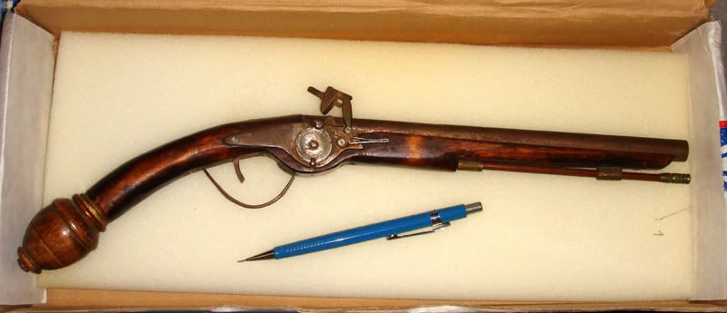
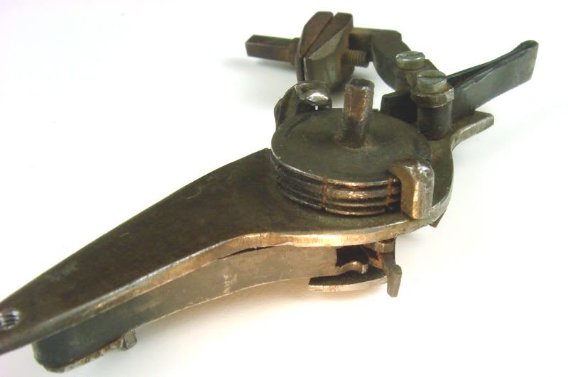
An overall view with a pencil for scale - it's a teenie one, all right.
DSC09293sml.jpg


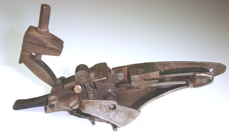
A view of the inside
DSC09294sml.jpg


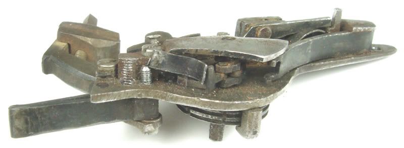
A bottom view showing the messed up pan cover arm return spring - someone drove a screw into it.
DSC09296sml.jpg


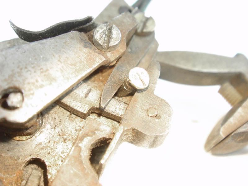
The above shot also shows one of the things that need fixing - the end of the bridle should have a piece going down into the lockplate, for the main spring to stop against rather than the chain having to stop it.

And speaking of the chain - it's a tad longer than it needs to be.
DSC09301sml.jpg


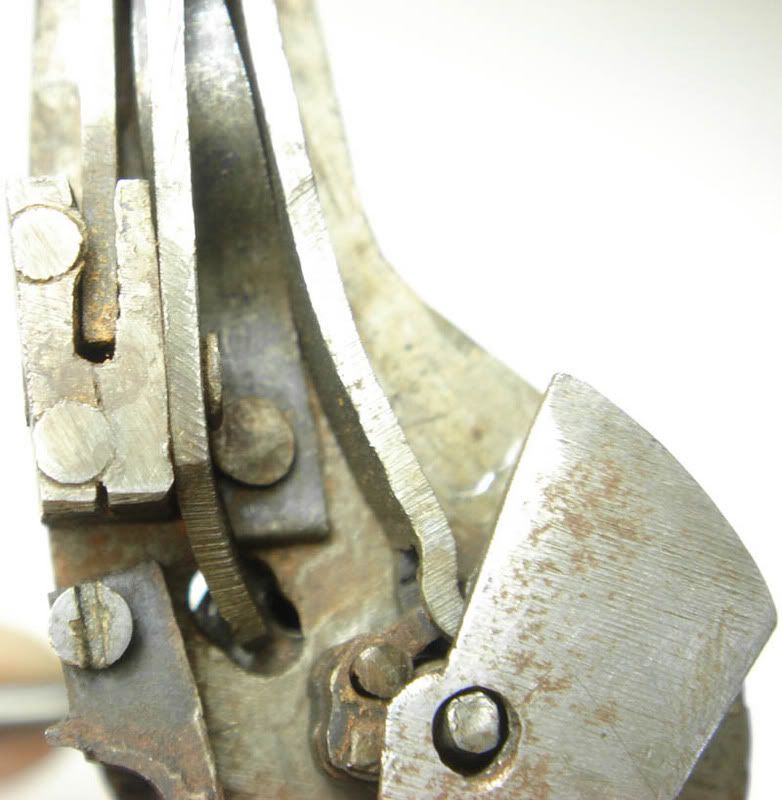
The sears seem to work sorta OK, but it would be nice to be able to work on them - alas, they are riveted in.
DSC09303sml.jpg


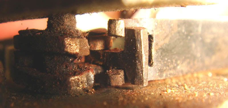
Here's a shot of the inside end of the brass thingie. It's the button that's supposed to release the pan cover and let its spring (the one that got trashed by a screw) push it closed.
DSC09304sml.jpg


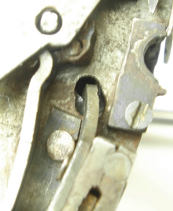
Here's a shot from the other direction, which also shows the break in the return spring (on the right). Note there is no bolster under the pan cover.
DSC09305sml.jpg


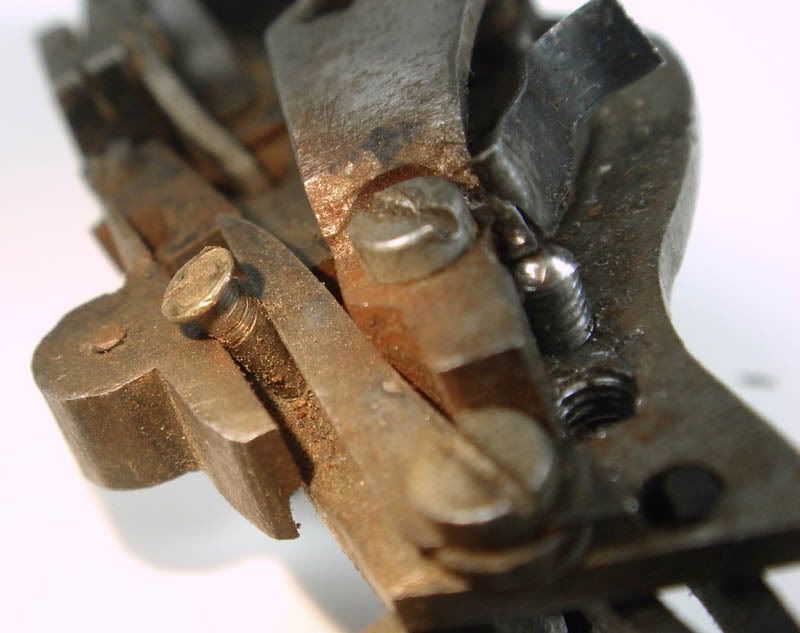
Here's the other end of the button, showing a slight interference with the dog-arm spring. The button really isn't practical on this tiny lock, anyway - not much room for a finger in there.
DSC09306sml.jpg


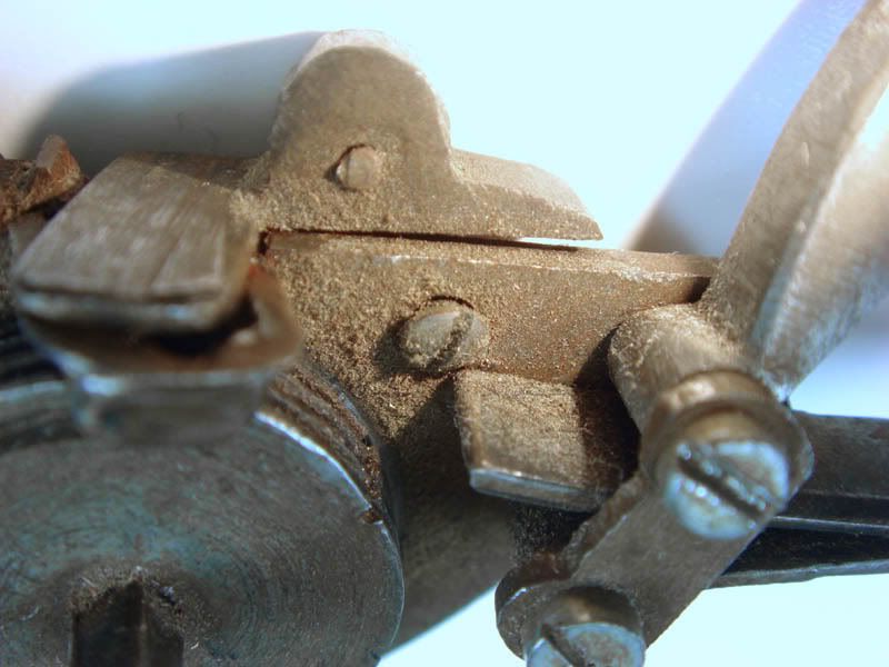
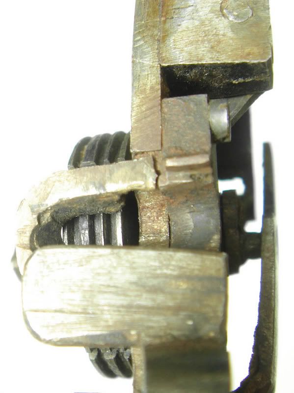
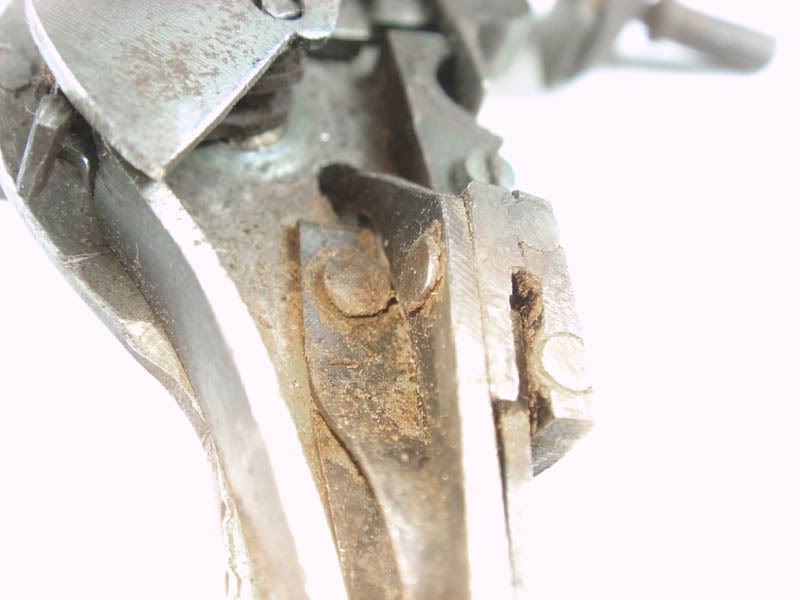
Another little issue is that the main spring is a bit too long. This shot shows where it is hitting the wheel shaft next to the lock plate.
DSC09309sml.jpg


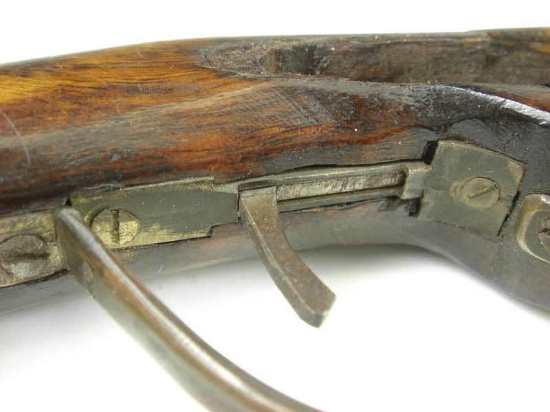
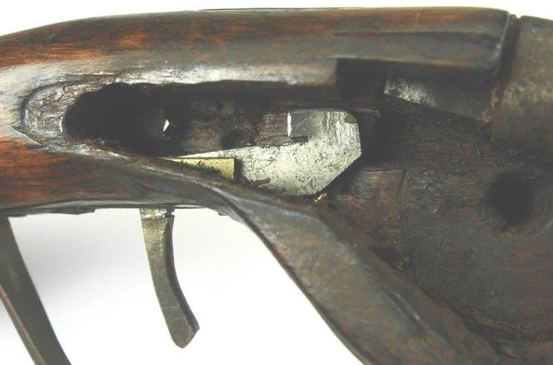
The trigger is very odd. It slides.
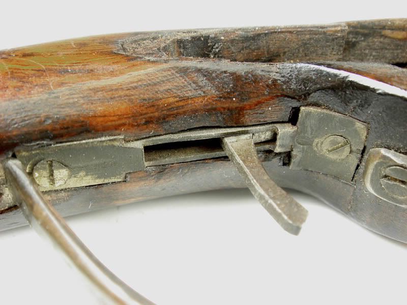
DSC09312sml.jpg

DSC09313sml.jpg


Here's the inside
DSC09314sml.jpg


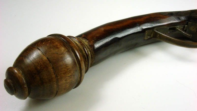
Here's a shot of the stock. Feels like pine.
DSC09315sml.jpg


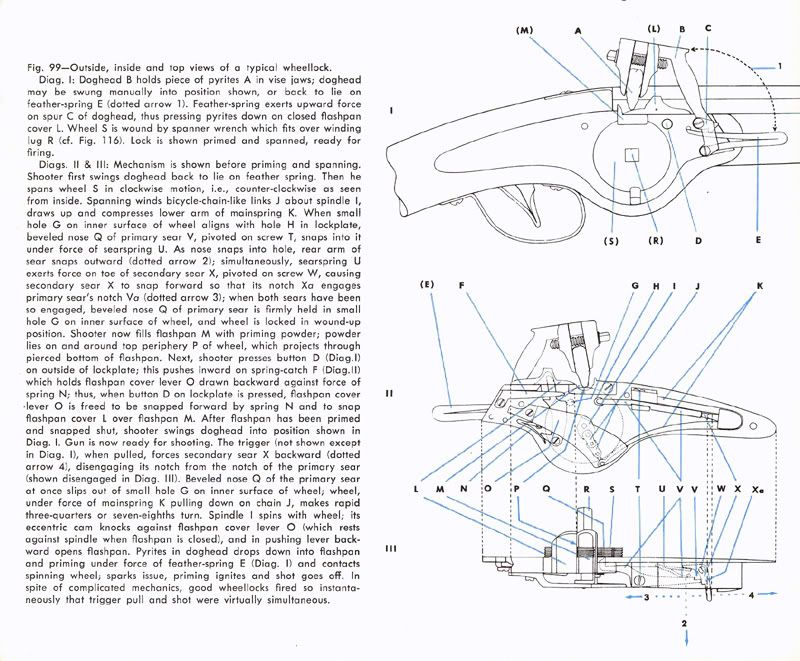
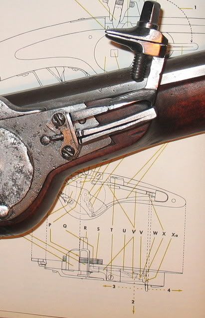
Interestingly, the diagram Tinker2 sent me is indeed for this very lock. It looks like the builder had only that diagram to work with. The diagram does not show the post at the end of the bridle to stop the spring, it doesn't show how the trigger is made, it doesn't show the bolster that is supposed to be under and supporting the pan cover - yup, the builder did a good job of following the diagram.

More later...
 
WRussel,
That is one messed up wheellock! One more thing wrong with it. If you ever did get it to spin on command, it would never scratch sparks off a pyrite. The circumferential ridges on the wheel have to be knife sharp to create the friction/heat necessary to make sparks. I believe the brass button was intended to be the pan cover retaining spring release button. It went drastically wrong at some point. I would rathe build a new lock!
God bless.
volatpluvia
 
OK, more observations on how NOT to make a wheellock.

As volatpluvia pointed out, the wheel needs sharp edged grooves - so does the pan, to keep the priming powder from trickling out through the grooves in the wheel. I gues that wasn't clear from the diagram, because the bottom of the pan where it "mates" with the wheel has no grooves. The pan also got filed down a little too thin and took a blow at some point that broke it.

I removed the button to free up the pan cover - even with the button untangled from the spring and pushed all the way out to the lock plate, the end of the button was still snagging the pan cover arm, which would not be good when the cam on the wheel shaft was trying to kick it open.

I also ground a little metal off the end of the mainspring and off the spot on the wheel shaft where it was hitting just before reaching "full cock". Didn't want to break anything tinkering. So now the wheel can be wound up all the way, but the sear does not enter the hole in the back of the wheel. And the wheel is retained by riveting, as is the sear. Hmmm...

I was hoping to at least get the thing sparking, maybe even put it in a pocket pistol, but as volatpluvia says - better to build a new one.

It would take a lot of rework to get it going, and then the main spring would be too weak, and then the chain would break, and then...

more in a bit
 
Here's a place where he didn't follow the diagram - the double spring for the sears should be tucked back out of the way - on this lock the main spring runs into it.
DSC09318sml.jpg


Here's the broken pan with no grooves to fit the wheel.
DSC09321sml.jpg


Here's the primary sear not lining up with the hole in the back of the wheel.
DSC09326cropsml.jpg


Educational? You bet. Worth working on? I don't think so.

Robin was right, as usual :v
 
Congratulations, a terrific lesson for me. That is a post that a wheellock builder should Save As Web Page Complete, it is a textbook for helping do it right the first time.
 
DSC09318sml.jpg


Is it me or is the hole in the bridle for the axle to big? It seams like with a hole that big it would have problems keeping the wheel strait as it spins.
 
Exactly right, the hole is way too loose. The hole for the shaft in the lock plate is loose also.

I'm not sure what the tolerances are there - you definitely don't want the grooves on the wheel rubbing against their mating grooves in the bottom of the pan, but the wheel is normally loose on the shaft, so the shaft alignment shouldn't be that critical (unless it causes more wear on the chain?). I would think that even with the hole in the bridle that sloppy, a wheellock would work fine, unless it's like this one, which has the wheel apparently pressed onto the shaft. Another oops.
 
WRussell-that Wheelock was STILLBORN :shake: !Thanks for posting the photos very educational.Good luck on fixing :shocked2: !
 
WRussel,
This is a case where the builder, and I use the term loosely, did not test anything as he went along. I all three locks I built so far I tested each component as I went along. Even though my second one does not light powder reliably, causing me to shelve it, I could not know that before it was fairly complete. Even so it works very smoothly, mechanically. This man made the pieces as he could best interpret the instructions and forged ahead even though what he had just added to the lock did not work!
God bless.
volatpluvia
 
Yes, too bad. A lot of work went into it. All wasted (unless he learned something).

What do you say, Robin? Pass it on to whoever wants to tackle fixing it?

BTW, here's the diagram Tinker2 sent (it originally had yellow lines but they were hard to see so I changed them to blue). If anyone knows where this diagram came from, we will have a date for the earliest the lock could have been made. Just out of curiosity.
frombjalexb.jpg
 
You guys are going to love this. I know that diagram looked exceedingly familiar. So I did some checking. That diagram is as far as I can tell strait out of The age of Firearms by Robert Held. Copyright 1957.
Unfortunately I can't offer you a page #. I had the book once and just scanned the pages that were important to what I was doing.
WRussell: If I'm not mistaken, I think you mentioned that you have this book?
Let me know what you all think.
Frost
 
Frost said:
You guys are going to love this. I know that diagram looked exceedingly familiar. So I did some checking. That diagram is as far as I can tell strait out of The age of Firearms by Robert Held. Copyright 1957.
Unfortunately I can't offer you a page #. I had the book once and just scanned the pages that were important to what I was doing.
WRussell: If I'm not mistaken, I think you mentioned that you have this book?
Let me know what you all think.
Frost
Hi Frost,
you are perfectly right. It is page 48 (bottom half) in my book printed 1957 (first edition I think). The text tells that many of the mechanical diagrams and most of the drawings of guns were made by Miss Nancy Jenkins.
BTW: A book that earns its place in my little library. :v
ARILAR :grin: :thumbsup:
 
Well my inventory says I have it but I can't lay my hands on it at the moment, so I'll take your word for it.

So this guy was probably working in the late 50's, early 60's. There wasn't much else available.

I think whoever did the drawing did a pretty good job, considering. Probably never took one apart, much less fired one. It just wasn't a very good drawing to build one from.

I think I'll make a copy of the drawing, with the info you've provided, and stick it in the box with the "gun". Actually, I could print it kinda small and put it in the cavity I found in the butt, after taking the pommel off. Plenty of room in there now that I've taken the gold coins out :rotf:
 
Found my copy - Interesting that the dwg in the book is in black and white, while the copy Tinker 2 sent me had those yellow lines. Oh well. I printed a copy to go with the pisstola.

Ha - bought a bottle of Pinot Noir the other day; the label is "Pinot Evil". The picture on the label is the famous three monkeys, see no evil, speak no evil, hear no evil, ..... :rotf:
 
I have been out of town. So my reply is a little slow.
I got the picture out of the New, Revised Edition of
The Age of Firearms. Page 48.

The book is dated 1957, 1970 and listed as the second
revised edition. Yes in my newer book the lines are yellow.
Much better looking and a lot easier to read after
WRussell darkened them to blue.

It would be a shame if it can’t be fixed. I was looking
forward to seeing a group project or group build if possible.

Thanks for the great pictures and your ability to diagnose
the problems.

Tinker2
 
Tinker2 said:
The book is dated 1957, 1970 and listed as the second
revised edition. Yes in my newer book the lines are yellow.
Tinker2

Funny,
In my first edition (1957) the lines are also yellow. Wonder what year Bill:s edition is printed? :rotf:

IMG_1359.jpg


ARILAR :grin: :thumbsup:
 
Sorry guys, I am a little confused about this... was this wheellock a mass-production kit that could be bought by your average builder and made into a functional wheellock back in the day? If so, where could I get a kit like this? I'm probably getting my hopes up over nothing, but if it concerns a wheellock, its worth asking.
 
Hangfeyer said:
was this wheellock a mass-production kit that could be bought by your average builder and made into a functional wheellock back in the day?
Sorry, think instead someone made a big effort to produce the lock (and pistol) only based on the drawing from the book "Age of Firearms". Probably already in the 60s. So...one of a kind.
ARILAR :grin: :thumbsup:
 

Latest posts

Back
Top