• This community needs YOUR help today. We rely 100% on Supporting Memberships to fund our efforts. With the ever increasing fees of everything, we need help. We need more Supporting Members, today. Please invest back into this community. I will ship a few decals too in addition to all the account perks you get.


    Sign up here: https://www.muzzleloadingforum.com/account/upgrades
  • Friends, our 2nd Amendment rights are always under attack and the NRA has been a constant for decades in helping fight that fight.

    We have partnered with the NRA to offer you a discount on membership and Muzzleloading Forum gets a small percentage too of each membership, so you are supporting both the NRA and us.

    Use this link to sign up please; https://membership.nra.org/recruiters/join/XR045103

Building a Chambers Little Fella's Rifle

Muzzleloading Forum

Help Support Muzzleloading Forum:

This site may earn a commission from merchant affiliate links, including eBay, Amazon, and others.
Joined
Nov 26, 2005
Messages
5,017
Reaction score
9,961
Hi,
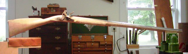
I will occasionally post photos and descriptions of my work on a Chambers Little Fella's rifle kit I am building for Rifleman1776. Frank wants a small light rifle and this kit should fill the bill. Despite building >60 muzzleloaders over the years, I've only built one kit gun. That was a Navy Arms 1863 Springfield musket. I bought a Chambers Pennsylvania fowler kit from a third party who had started it but he had buggered it too badly for the stock to be salvaged. Anyway, this is the first Chambers kit that I will build from the start. I examined many Chambers kits over the years and believe they are mostly very good offerings. This one, however, is not one of their best and I will get into that as I go along. Regardless, it will turn out fine in the end.
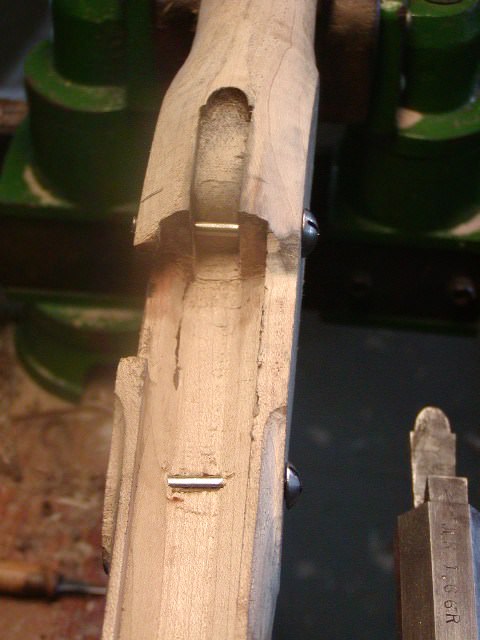
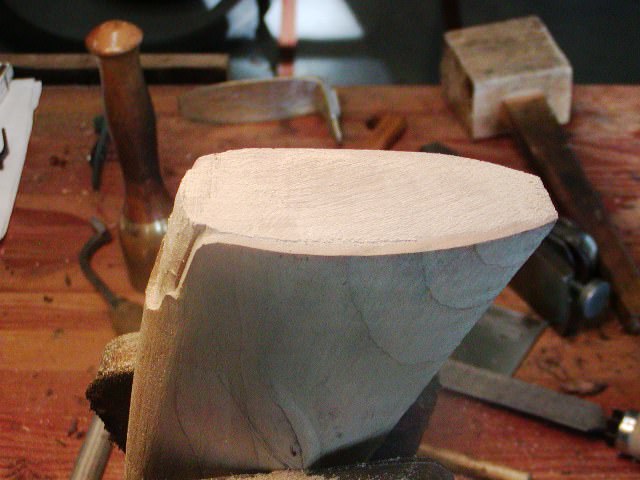
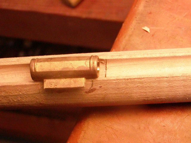
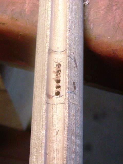
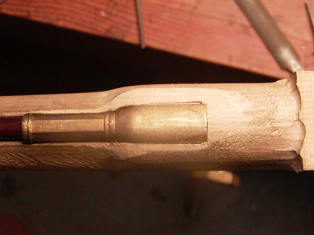
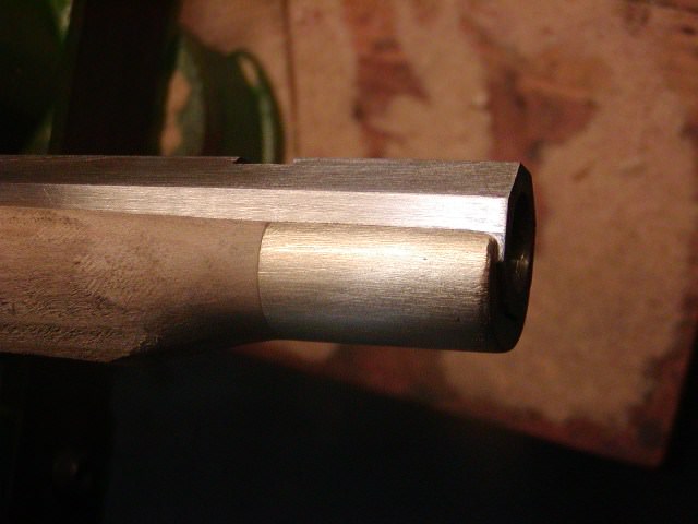
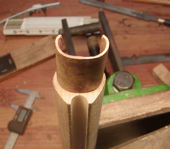
I am going to turn the rifle into an early Berk's County style gun as much as I can. The stock has a lot of extra wood so I have room to maneuver. The first step is to seat the breech of the barrel. It needs to slide back about 1/8" so the vent hole can be located in front of the end of the breech plug.
r3cWKyR.jpg

The stock shaper cut the inlet for the breech plug bolster and breech of the barrel too deep. I am going to seal the barrel channel with a varnish thin coat of AcraGlas anyway, so that will fill in the space. The barrel needed to be inlet a little deeper overall so that the vent hole would be level with the pan of the lock. You don't have any room to shift the lock around because the inlet for it restricts it to one position to avoid any gaps (more about that later). Anyway, lowering the barrel eliminated most of the void at the breech.
AZUZBDb.jpg

WsioKc6.jpg

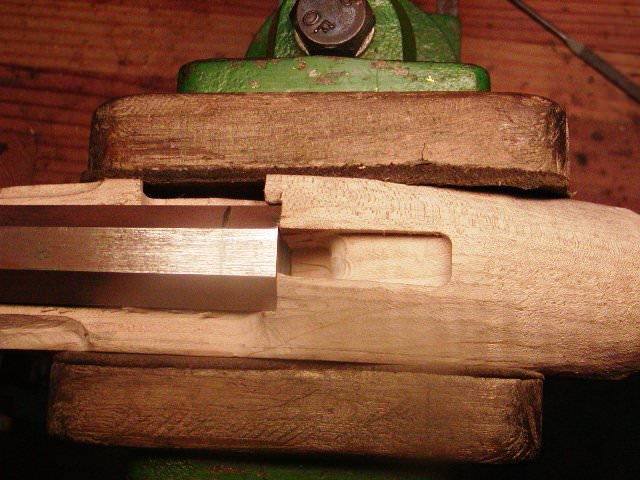
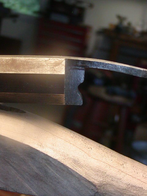
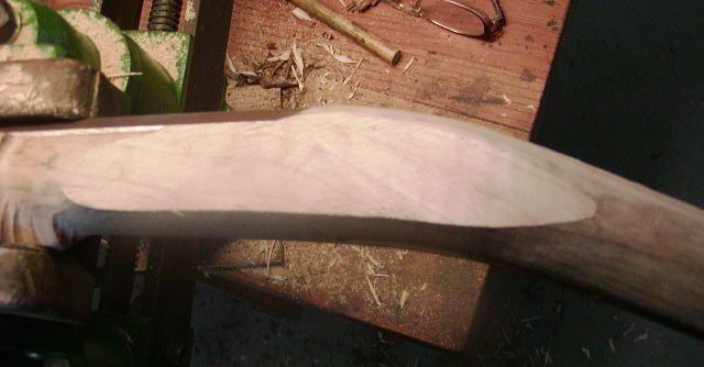
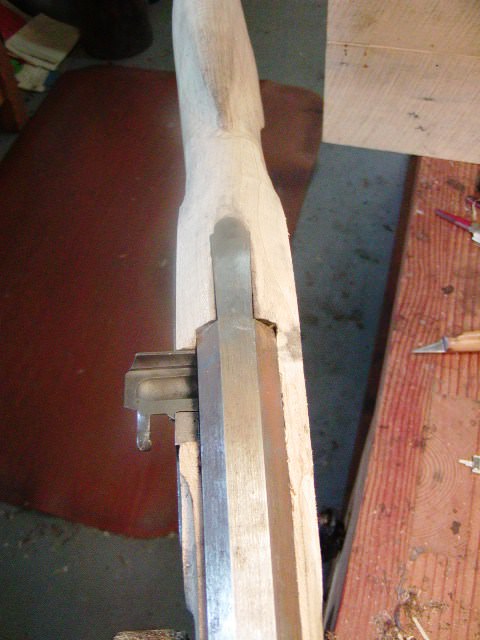
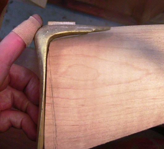
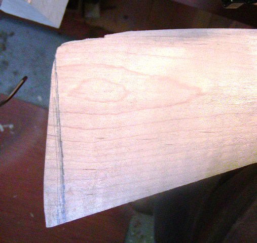
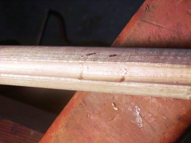
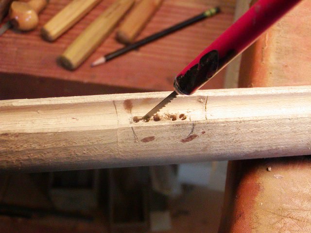
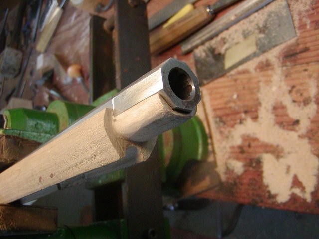
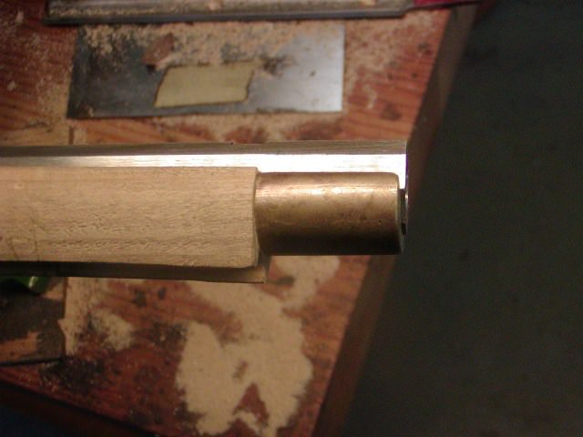
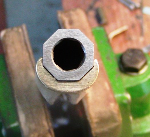
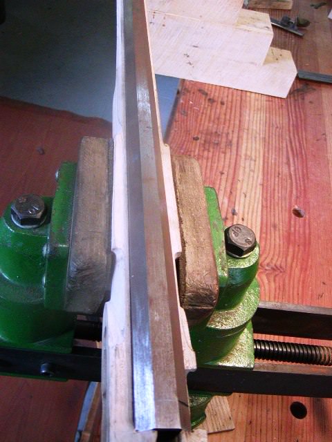
Next I wanted to thin the web of wood between the barrel channel and the ramrod groove. Note how much extra thickness there is below the bottom of the muzzle cap. That means the ramrod will hang below the cap with an obvious gap. No gun will ever go out of my shop looking like that. The ramrod hole is already drilled so I cannot move it. Instead, I scraped and filed the groove so the web of wood thins toward the muzzle. The small taper won't affect the rod going in and out but it improves the appearance tremendously by slimming the forestock. Further, I will deepen the groove right near the muzzle so it can accommodate a substantial swell in the ramrod tip. I will discard the 3/8" rod that came with the kit and use one of my 7/16" rods that will be tapered to fit the gun and have a swell at the end.
M9unBdP.jpg

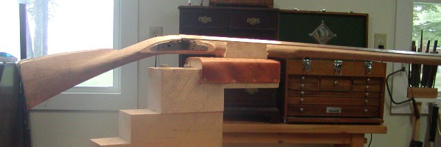
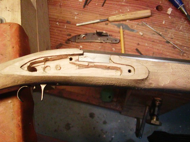
As you can see there is a lot of extra wood along the forestock that will be removed. A lot of extra!
cWf1NGN.jpg

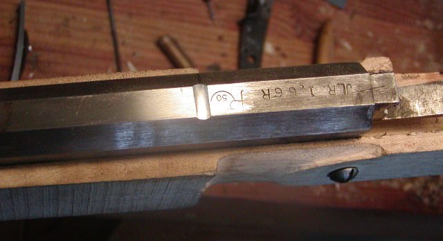
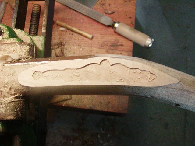
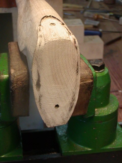
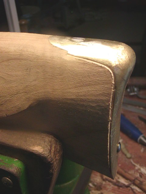
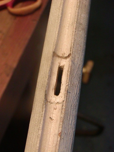
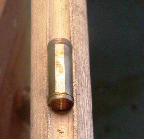
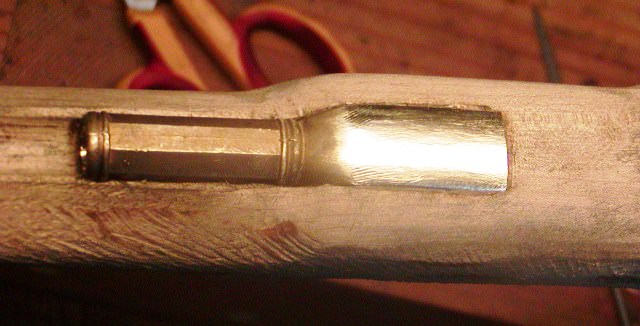
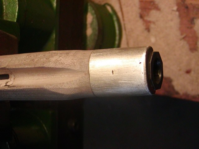
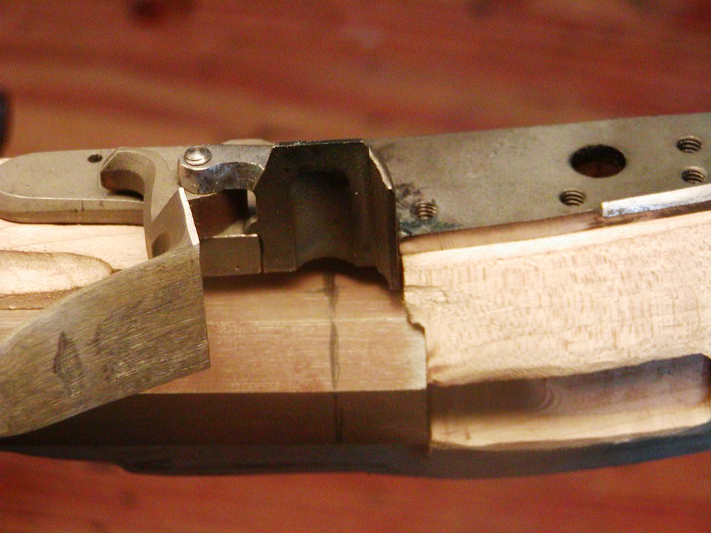
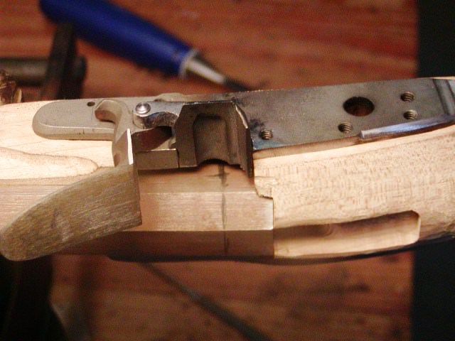
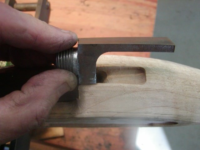
I inlet the breech plug. The plug is well fitted to the barrel and I reshaped it to look like those commonly seen on early Berk's guns. I would have liked to narrow it a bit but the machined inlet requires the full width of the plug near the end. Before inletting, I filed away the radius between the bolster and under side of the tang. That radius really makes inletting difficult. Instead, I always file the plug square despite the inlet having a radius on top. However, by moving the barrel back, I eliminated most of that radius. I filed draft on the edges of the tang and inlet it, which went easily.
JjAfon3.jpg

WsioKc6.jpg

3hRyv2Z.jpg

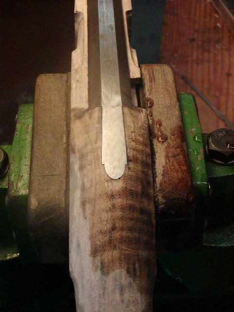
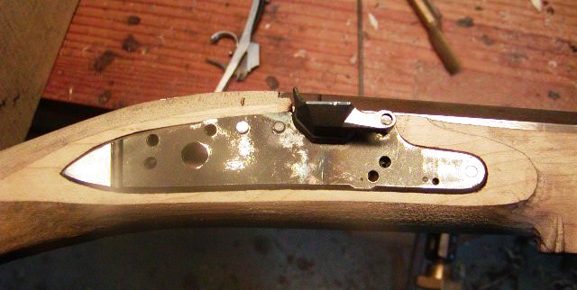
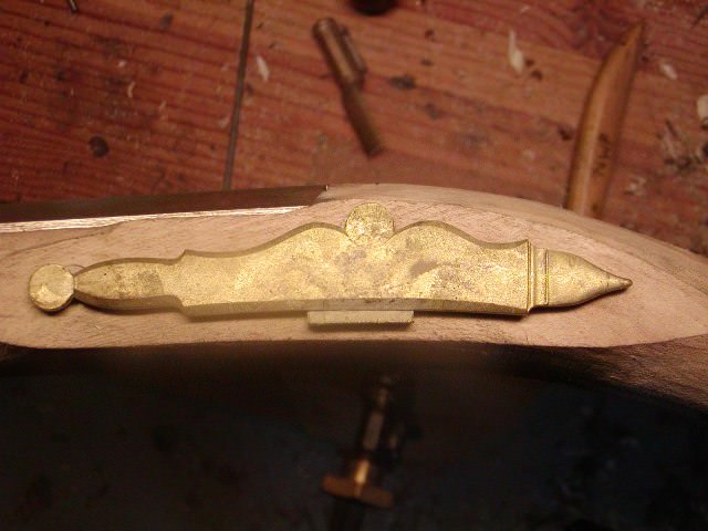
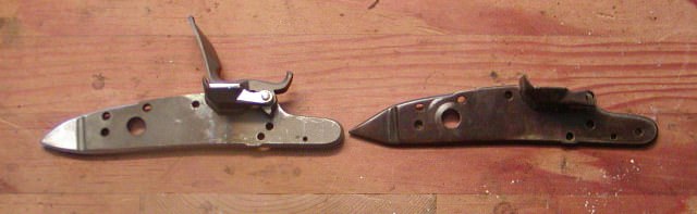
Next up is inletting the lock. Unfortunately, this Siler lock had some issues. The internals are fine and it works very well, but the pan and bolster were poorly fitted to the plate, something I never encountered on a Chambers-built Siler before. Moreover, the lock barely fills the machine inlet and there are tiny gaps around the tail of the plate. I suspect those gaps would disappear when the lock is fully inlet and finish is applied. However, I won't take those chances and I really don't much like the triangular tail of a Siler anyway. Many of the early Berks rifles had locks with thicker and slightly more rounded tails. So, I got out my welder, fixed the fit of the pan and added metal to the tail. Shaped the tail and also reshaped the pan bridle to get rid of the ugly one on the Siler. The result is HC and looks pretty good. Well, that is where I am and I will post some more soon. I am building this rifle and also am well on my way building a late flint English rifle, which I have to turn my attention to for a few days.
dave
OiFlSzS.jpg
 
Dave
Thanks for the update. Seeing what will probably be my last gun acquisition ever is very exciting. From your explanations, we can see the Chambers kits, while good, are not a simple 'click, click, snap, snap' assembly job. They do require an experienced builder.
I'm blessed to have one of our premier builders working mine.
 
Thanks for looking folks,
I worked on the rifle yesterday. I inlet the lock plate after filing draft on all edges. It went in nicely and tight. I'll do the internals later.
mJFxS9c.jpg

I drilled the plate for the lock screws and threaded the holes for 8-32 bolts. Then leveled the stock in my drill press vise, and drilled through the lock plate holes and the stock with a drill smaller than the holes. I centered the forward lock bolt on the nose of the plate but that meant the hole breaks into the barrel channel a tiny bit. Unfortunately, there is no way to avoid this unless you drill the hole off center in the lock plate. You cannot reposition the lock because it is pre-inlet. I am sure I made the break through worse by burying the barrel a little deeper so the vent hole will be level with the top of the pan.
1ZIWyTU.jpg

Of course, none of this is a problem. The solution is a shallow groove on the bottom of the barrel to clear the bolt. Probably a quarter of the guns I've made and many originals I've examined have this same feature.
r9J9K8w.jpg

The same issue occurs with the rear lock bolt. You cannot move the hole far enough back on the lock bolster to miss the breech plug bolster without hitting the little tab on the lock bridle. Again, this is not a problem, just either drill a hole for the bolt through the plug bolster or notch its back edge. I simply notched it with the shape of the notch allowing the barrel to be removed and inserted without removing the lock bolt. You see this on many originals. A warning, however. Make sure the hole or notch has enough slop in it so that it does not rest against the bolt. During recoil, the barrel will push back on the bolt if it is tight up against it and the bolt could act like a wrecking bar on the stock. I had that happen on a pistol. The rear bolt cracked the stock at the bolt hole. With the holes drilled and notches filed I ran a pulley tap through the bolt holes into the back of the plate and freshened the threads. That assures the bolts thread in nice and easily.
9xrdJDh.jpg

You may have noticed that when drilling the lock bolts, I did not care about the holes lining up with the side plate and side plate inlet. That is because I am not going to use that plate and there was sufficient extra thickness in the stock for me to wipe out the entire pre-inlet. When you click on the Little Fella's Rifle on Jim Chambers' web site, you see an image of a rifle designed and made by David Dodds. David died some years ago and he was one of the finest makers around. His little rifle was a nice blend of Berks and York county features including a really nice Berks side plate. The kit does not have that plate. It provides a generic English fowler plate that IMO is too large and not appropriate for what I am trying to do with the kit.
U7swMLU.jpg

0TIbWgd.jpg

I am going to try and make it closer to an original Berks gun. Fortunately, there is enough extra wood to get rid of the side plate inlet and keep the stock thickness even on both sides. I get to the side plate later.
LkYtLAE.jpg

zggmjaD.jpg

I decided to get the buttplate done so I can determine what potential LOP I can devise. The BP is a very pleasing design but the inlet had some issues. The angle of the pre-inlet angles the toe too far back causing the comb of the plate to be out of line with the comb of the stock. To correct this, I trimmed off the toe of the stock to realign the BP. It all worked out fine and easy using my bandsaw, a pattern maker's rasp and some chisels. The other secret is the ball pen hammer. When you have the butt plate fitted pretty close, fit the screws and then beat the snot out of the edges of the plate to close any tiny gaps. This works great with brass, not so well with steel.
gfxzATo.jpg

OVZBkeK.jpg

P7dgiNe.jpg

VhosM5E.jpg

GoV80Ww.jpg

Well here is the long view for now at the end of the day.
dqRVuZP.jpg


dave
 
Dave, nice to see and show how a kit can be customized by going for another sideplate. What length of pull did you get?
 
Hi Rich,
I should get about 13" LOP if I can position the set triggers correctly. If I was using a simple trigger that would be a no brainer but with the double lever set trigger with which the owner expects to be able to fire the gun with the trigger set or not, positioning is much less flexible. As you can see from the photo showing a top down view after filing off the sideplate inlet, the stock is still thicker on the side plate side compared to the lock side. There is just a lot of extra wood left everywhere on the stock except around the pre-inlets.

dave
 
Dave
Thanks for the update and pics. All very exciting. Much in your post I could comment on. But will stick with just two. The entire story of the build shows just why a custom ml rifle is not a cheap endeavor. When finished, they look simple. e.g. stock, barrel, lock. But the complexities involved are not obvious. Your talents are special. The other comment involves the butt plate. When I built my Navy Arms (Pedersoli) Brown Bess kit installation of the butt plate was a major frustration for me. I finally turned the job over to an experienced builder. That task beat the snot out of ME. :wink:
 
thanks for putting this project on the forum, I really like this forum! I purchased an Early York kit from Jim Chambers at the 2018 Dixon's Muzzleloading Expo and will be building it this winter in Pa. I have 2 videos on building these fine rifles and I feel I can never get enough info from all of the experienced builders on this site! Thanks everyone! :bow:
 
Hi Folks,
Thanks for looking and off I go with a little more. Yesterday I inlet all the ramrod pipes and the muzzle cap. The forward pipes were easy. The machined inlet removes most of the wood volume required and you just have to cut the slot for the tab and lightly chisel the mortice to fit the pipes.
0GTZLhq.jpg

RW9CJTI.jpg

By the way Frank, that is my blood on the side of the stock. I am now one with the your wood.

I hand draw a centerline where the tab will go. Then I drill a series of holes and cut between the holes with a fret saw blade held in an X-acto blade handle. After that a few swipes of a flat needle rasp and the slot is done.
sjU4hur.jpg

rOlDWY6.jpg

uBBQH4n.jpg

Then I insert the pipe, trace around it with a sharp pencil. I chisel and scrape out to the pencil line with a small shallow gouge until the pipe sits down a little into the mortice. Then I blacken the pipe and remove wood with a small gouge until the pipe sits down all the way. The forward pipes only took me about 45 minutes to inlet.
mqosSHx.jpg

The rear pipe was another story. I really, really wish Chambers left the mortice for the rear pipe tang uncut. The job was botched such that the machine inlet was too wide creating gaps on the sides of the tang. In addition, this diminutive rifle should have a narrower tang on the pipe in line with its proportions. Anyway, I inlet the pipe much as the others except for inletting the tang. Because the ramrod hole is already drilled I cannot inlet the pipe deep enough to erase the gaps, so I glued in some wood slivers that fit nicely in the gaps and let it go at that. The fix will be virtually invisible once the stock is stained.
3nouRHH.jpg

sLqgft2.jpg

Next up was the muzzle cap. A cast "Bivens" cap was included with the kit. These sturdy caps are made to look like early "one-piece" caps hammered from sheet brass. I am not a big fan of them because they leave very little wood left between the barrel and the cap. My first task was to grind away some of the brass from the inside using a grinding stone and a Dremel to thin the cap overall. That allowed me to preserve more wood. I squared up the end of the cap to make a nice straight surface to mate with the wood, and filed a little on the front to fit the barrel nicely. Then I just rasp, file, cut and scrap wood away until it fits snugly in place.
dbb4DPy.jpg

8KhYEgg.jpg

orG3Kci.jpg

vsPlu7Q.jpg

On early Reading guns, these one piece caps were often attached using a counter sunk screw from the bottom that threaded into the barrel. I will simulate that by inletting a thin square nut into the barrel channel and have the screw thread into that rather than the barrel. I built several guns in the past with the screw threaded into the barrel and I found most folks forgot to remove that screw when removing the barrel so I make a "faux" barrel screw. Well that was yesterday's work. Today I installed the lock, triggers, and tang bolt. I'll show that tomorrow.
dave
 
Hi,
One thing to add about the muzzle cap. The first photo shows the cap with the stock before I began work. The gap between the ramrod channel and the cap would result in the ramrod tip hanging below the muzzlecap with obvious space between them. That always looks awful to me so I chiseled and scraped the ramrod groove so the web of wood between the barrel and groove thins toward the muzzle.
M9unBdP.jpg

As you can see in the next photos, the step is gone.
vsPlu7Q.jpg

YjbOMzK.jpg

Yesterday, I finished inletting the lock. The machine inlet was OK and only a little more wood had to be removed in front of and around the mainspring. However, because I lowered the barrel to align the vent hole properly, the mainspring no longer clears the barrel and the inlet breaks into the barrel channel. Consequently, I simply ground a bevel on the upper leaf of the spring, which allowed it to clear the barrel. I still have to clean up the lock mortice a little but for now it is done.
UEO55fq.jpg

Next was the set triggers. The kit is designed for a single trigger and the guard has just enough space inside it to allow double set triggers but it is very close. The Davis set triggers supplied are fine, however, I hate the flimsy wire springs used on the front triggers. Therefore, I made my own more robust spring.
06rBsnc.jpg

The triggers can be installed so the gun can be fired by pulling the front trigger without setting the rear. Unfortunately, because the triggers are pinned through the trigger plate and as such the pivot is low, they get little leverage on the sear and it is very hard to give the front trigger a nice light pull and good feel. They usually end up with heavy pulls without the rear trigger set. Hence, the heavier wire spring, which provides a little power assist to the front trigger and assures the set engagement is very solid as well. The heavier spring has to be balanced with the sear on the lock so it does not interfere with cocking the lock. But when adjusted right, it helps make the front trigger pull lighter and crisper. The trigger blades or bars had to be ground down to about 1/3 of their original heights to make them work on the gun and allow the lock to be cocked without setting the triggers. I also wanted the rear set trigger to be as far back in the trigger guard bow as possible so I could keep as much space as possible in front of the front trigger. That way, Frank has plenty of space to slide his trigger finger into place without risking an accidental firing. I installed a wood screw in the rear of the triggers and drilled and tapped a hole in the front for the tang bolt. I had to cut off the front of the trigger plate to clear the forward lug on the trigger guard. As it is, I will still have to file a slot or notch in the front to provide for that lug. You can see the front of the machine inlet showing. It will be covered by the trigger guard.
t6yDaiG.jpg

I fitted the tang bolt. I don't just counter sink them into the tang. First I turn a flat or shoulder on the edges of the tang bolt head. Then I counter bore the hole in the tang by choosing a drill the diameter of the bolt head. I drill into the tang just far enough so the hole has shallow vertical sides. Then I use a counter sink to cut the bottom of the hole to shape for the screw head. I continue to cut the counter sink until the bolt head fits down nicely in the hole. The advantage to this is that the head is stronger and can have a deeper screwdriver slot. Second, if you need to file the head to fit a rounded or angled surface, you have more mass of metal to work with and no risk of under sizing the head to the counter sunk hole.
5kwfAFN.jpg

lRNQTwL.jpg

Well, here is where I am. As I look at the gun, I can see where I need to make some changes in architecture to get it to look right. It looks a bit clumsy to me but I think I can take care of that. As I start shaping I admit that I may ultimately fill the ramrod hole with a maple dowel, inlet the rear pipe deeper and re-drill the hole. I fear that the forearm will look too deep and bulky for the size of the gun. I prefer that the bottom of the stock taper gently upward from the triggers to the rear pipe. As it is now, the bottom is even all the way to the rear pipe and it almost looks like bottom may have a very slight downward bulge at the pipe. That is not my ideal but if you look at rifles #20 and #22 in "Rifles of Colonial America" and the first rifle in David Hansen's "An Intimate Look at the American Longrifle: It's Art and Evolution", you will see that those Reading guns seemed to have a slight bulge at the rear pipe. Reading guns have a unique shaped step at the rear pipe and uniquely shaped ramrod groove moldings, which I will demonstrate. Anyway, I will mull over what to do as I shape the gun. More to come but I have to work on another rifle for a few days.
dave
Jryk3gW.jpg
 
Hi,
I apologize. I reread my last post this morning and I really did a lousy job describing the value of the heavier wire spring on the set triggers. I think I was tired of writing so tried to short cut the explanation but it seems very misleading to me when I read it again this morning. The spring pushes the front trigger up in front forcing the trigger blade down. When you set the triggers, the action of the tip of the notch on the rear trigger clicking over the tip of the notch on the front trigger often causes the front trigger blade to flick upward, sometimes quite high, when it is held down by a flimsy wire spring. The force can be sufficient to set off a lock at full cock if the blade hits the sear. The solution to this is to grind the front blade down low enough below the sear such that it does not hit the sear when the triggers are being set. When that is done, the trigger pull without the rear being set has a lot of creep as the blade on the front trigger has to rise up a bit before touching the sear. Also, the trigger at that point has lost a lot of leverage against the sear and it is hard to get a nice trigger pull. My heavier wire spring keeps the front trigger blade from flicking up when the triggers are set. That allows me to grind down the front trigger blade so that it touches the sear or is a hair below it at rest and still enable the set function to work properly. Therefore, you have little or no creep in the trigger when unset and you don't lose any leverage.

dave
 
Thanks again for your expertise! Please keep doing these updates, the information will be put into building my rifle this winter, Thanks! GREAT job!
 
Back
Top